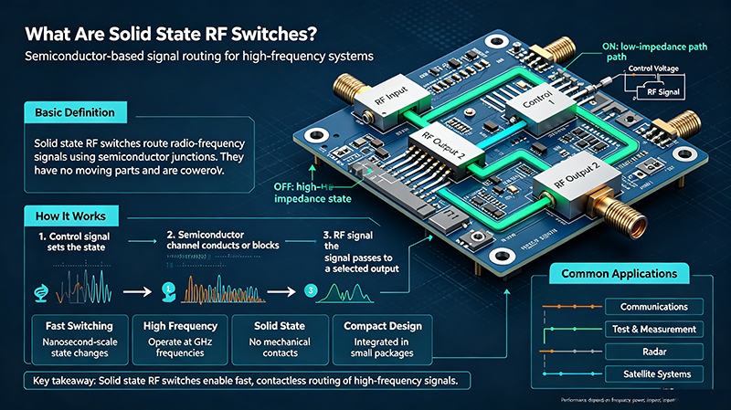
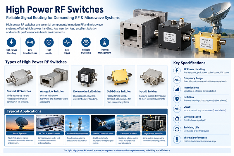
RF switches are essential components in modern wireless communication, radar systems, test equipment, and satellite applications. Among the most commonly used configurations are SPDT, SP4T, SP6T, and SP12T RF switches. Understanding these switch configurations helps RF engineers select the right solution based on signal routing requirements, frequency range, isolation, insertion loss, and system complexity.
This guide explains the differences between SPDT, SP4T, SP6T, and SP12T RF switches, their working principles, advantages, typical applications, and key selection considerations.
What Is an RF Switch?
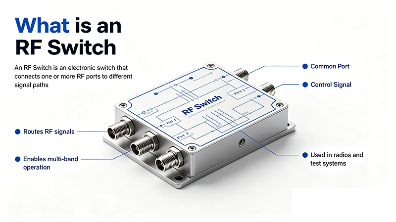
An RF switch is a device used to control the connection between multiple RF signal paths. It allows an RF signal to be routed from one input port to one or more output ports while maintaining signal integrity at high frequencies.
RF switches are widely used in applications such as:
- Wireless communication systems
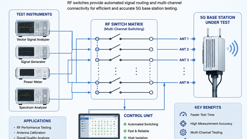
- 5G network testing equipment
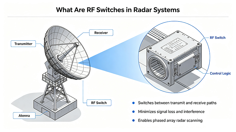
- Radar and electronic warfare systems
- Satellite communication systems
- RF automated test systems
- Microwave measurement instruments
Understanding RF Switch Configurations
RF switch configurations are commonly described using the SPxT format:
SP = Single Pole
Represents the common RF input or output port.
T = Throw
Represents the number of selectable output or input paths.
For example:
- SPDT: Single Pole Double Throw (1 input, 2 outputs)
- SP4T: Single Pole Four Throw (1 input, 4 outputs)
- SP6T: Single Pole Six Throw (1 input, 6 outputs)
- SP12T: Single Pole Twelve Throw (1 input, 12 outputs)
SPDT RF Switch
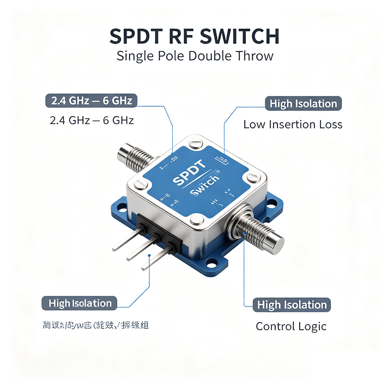
An SPDT RF switch is one of the most widely used RF switch configurations. It contains one common port and two selectable RF paths.
SPDT RF Switch Structure
The basic operation is:
- Port 1 connects to Port 2
- Port 1 connects to Port 3
- Only one RF path is active at a time
Applications of SPDT RF Switches
- Antenna switching
- Transmitter and receiver isolation
- RF test equipment
- Wireless communication modules
SP4T RF Switch
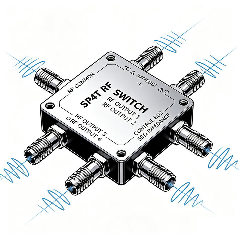
An SP4T RF switch provides one common port and four selectable RF paths. It is commonly used when multiple signal channels need to be controlled within a compact system.
Advantages of SP4T RF Switches
- Supports multiple RF routing options
- Reduces system hardware complexity
- Suitable for multi-channel RF systems
- Improves test system flexibility
Typical Applications
- RF calibration systems
- Communication testing platforms
- Multi-band wireless equipment
- Laboratory measurement systems
SP6T RF Switch
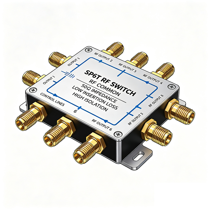
An SP6T RF switch expands the switching capability to six RF channels. It is commonly used in systems requiring more signal routing options while maintaining high RF performance.
Common Applications of SP6T Switches
- 5G testing systems
- RF production test equipment
- Multi-antenna systems
- Defense communication systems
SP6T switches provide a good balance between switching capacity, size, and insertion loss performance.
SP12T RF Switch
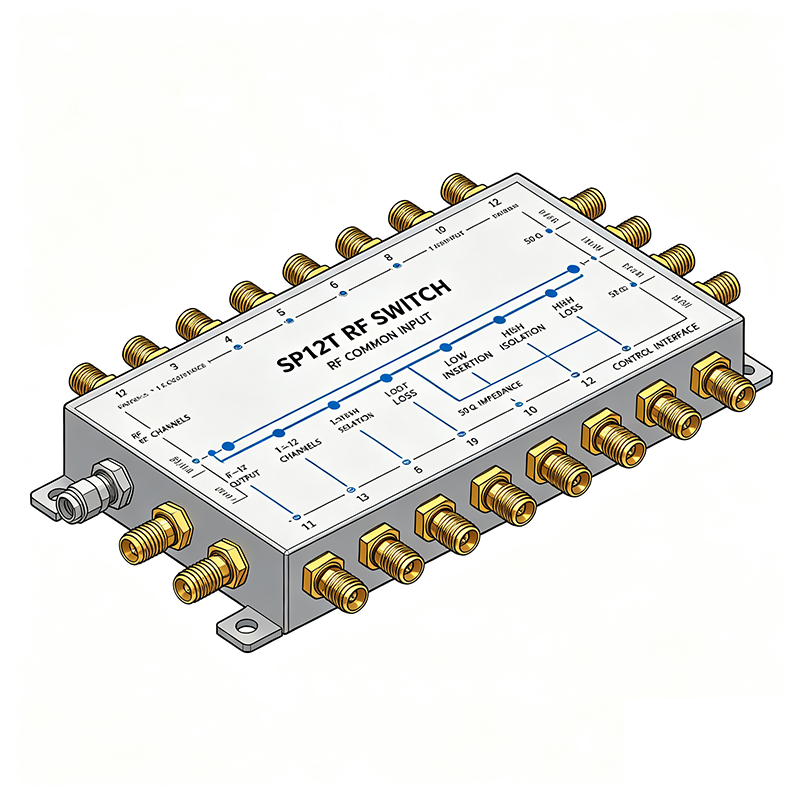
SP12T RF switches provide one input port and twelve selectable output channels. They are designed for complex RF systems requiring extensive signal routing capability.
Advantages of SP12T RF Switches
- Large number of selectable channels
- Reduces the need for multiple switches
- Supports complex RF test environments
- Improves system integration efficiency
Applications
- Automated RF testing systems
- Satellite communication equipment
- Radar measurement systems
- Advanced wireless research platforms
SPDT vs SP4T vs SP6T vs SP12T RF Switch Comparison
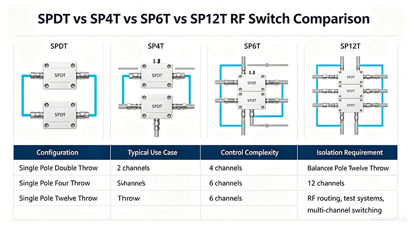
| Configuration | Ports | Main Advantage | Typical Applications |
|---|---|---|---|
| SPDT | 1 Input / 2 Outputs | Simple design and low insertion loss | Antenna switching, RF modules |
| SP4T | 1 Input / 4 Outputs | Flexible multi-channel switching | RF testing, communication systems |
| SP6T | 1 Input / 6 Outputs | Higher channel capacity | 5G testing, defense systems |
| SP12T | 1 Input / 12 Outputs | Maximum routing flexibility | Complex microwave systems |
How to Choose the Right RF Switch Configuration
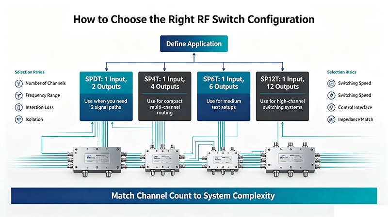
Selecting the correct RF switch depends on several important parameters:
1. Number of RF Channels
The required number of signal paths determines the switch configuration. Simple systems may only need SPDT, while advanced test systems may require SP12T.
2. Frequency Range
RF switches must support the operating frequency range of the system. Microwave and millimeter-wave applications require switches designed for high-frequency operation.
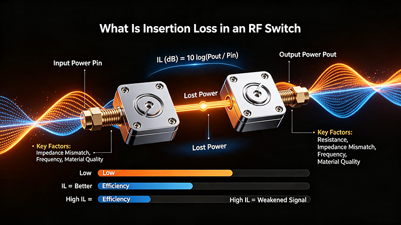
3. Insertion Loss
Lower insertion loss improves signal quality and reduces power attenuation, especially in high-frequency applications.
4. Isolation Performance
High isolation prevents unwanted signal leakage between unused channels and improves system reliability.
5. Switching Speed and Reliability
Applications such as radar and automated testing often require fast switching speed and long operational lifetime.
Applications of SPxT RF Switches
SPDT, SP4T, SP6T, and SP12T RF switches are widely used in:
- Radar Systems: Signal routing and antenna control
- 5G Testing: Multi-channel RF measurement
- Satellite Communication: Reliable signal switching
- Defense Electronics: High-performance RF control
- Wireless Networks: Antenna selection and optimization
Conclusion
SPDT, SP4T, SP6T, and SP12T RF switches provide different levels of signal routing capability for modern RF and microwave systems. SPDT switches are ideal for simple switching tasks, while SP4T, SP6T, and SP12T configurations support increasingly complex multi-channel applications.
When selecting an RF switch, engineers should carefully evaluate frequency range, insertion loss, isolation, power handling, switching speed, and application requirements. Choosing the right RF switch configuration ensures better signal performance, system reliability, and long-term operational stability.