




























What Is an RF Coupler? How Does an RF Coupler Work
Table of Contents
1. What Is an RF Coupler?
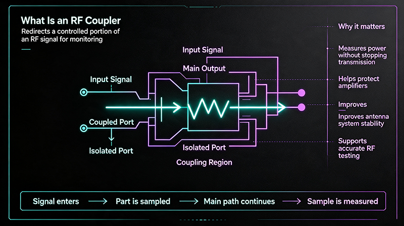
An RF coupler is a four-port passive device that splits an incoming signal into two paths. Most of the signal passes through from the input to the output, while a small, known fraction is diverted to a coupled port. The isolated port is terminated to absorb any backward-traveling signal.
RF couplers are used for power monitoring, signal sampling, feedback loops, signal injection, and combining. They are essential in test & measurement, radar, telecommunications, satellite, and broadcast systems.
2. How Does an RF Coupler Work?
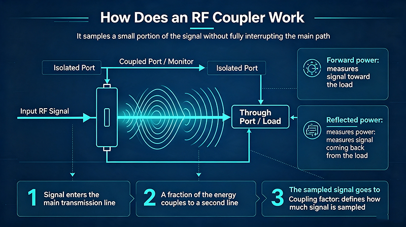
RF couplers rely on electromagnetic coupling between two transmission lines. Two main physical mechanisms are used:
- Loose / aperture coupling — two microstrip or stripline traces are placed close enough that a controlled amount of energy couples across the gap.
- Transformer coupling — a ferrite core or transmission-line transformer divides the signal by a precise turns ratio.
The amount of signal diverted is the coupling factor, expressed in dB. A 20 dB coupler routes 1/100th of the input power to the coupled port.
3. Types of RF Couplers
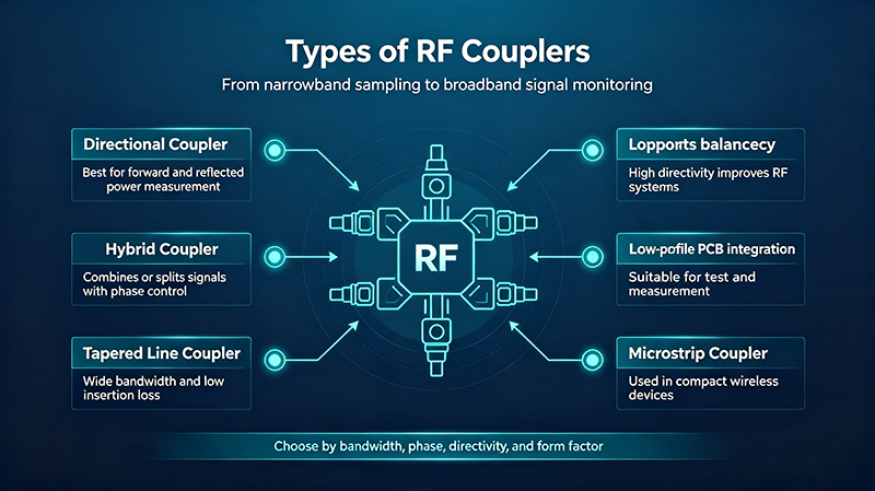
3.1 Directional Coupler
The most common type. It is directionally sensitive — it samples signal traveling only from input to output, not in reverse. Typical coupling values: 6, 10, 20, 30 dB.
3.2 Dual Directional Coupler
Contains two directional sampling paths in one package — one for forward power, one for reflected power. Used in radar and VSWR monitoring.
3.3 Hybrid Coupler (90° / 180°)
Splits input power equally between two outputs with a defined phase relationship. The 90° hybrid is used in I/Q modulators, image-reject mixers, and feed networks. The 180° hybrid (rat-race) combines or splits signals with 180° phase difference, common in balanced amplifiers.
3.4 Wilkinson Power Divider
An N-way power splitter/combiner with high isolation between output ports. Widely used in feed networks, MIMO antennas, and power-combining amplifiers.
3.5 Bidirectional Coupler
A coupler that samples signals in both directions using a single coupled port. Often paired with a detector to measure forward and reflected power.
3.6 Lumped-Element Coupler
Built with discrete inductors and capacitors instead of transmission lines. Used at low frequencies (HF/VHF) where distributed designs would be too large.
| Coupler Type | Power Split | Phase | Typical Use |
|---|---|---|---|
| Directional | Unequal (e.g. 20 dB) | In-phase | Power monitoring |
| Dual directional | Unequal | In-phase | Forward/reflected power |
| 90° hybrid | Equal (3 dB) | Quadrature | I/Q modulators |
| 180° hybrid | Equal (3 dB) | Anti-phase | Balanced amplifiers |
| Wilkinson | Equal (N-way) | In-phase | Antenna feeds, MIMO |
| Bidirectional | Unequal | In-phase | Inline power sensing |
4. Key Specifications Explained
Coupling Factor
The ratio of input power to coupled-port power, in dB. Common values are 6, 10, 20, and 30 dB.
Directivity
Difference between forward-coupled and reverse-coupled power. Higher directivity means better rejection of unwanted signals. > 20 dB is good; > 30 dB is excellent.
Insertion Loss
Loss between input and output ports. A 20 dB directional coupler typically has < 0.2 dB insertion loss.
Frequency Range
The bandwidth over which the coupler meets its specifications. Wideband couplers cover multi-octave ranges.
VSWR (Return Loss)
Impedance match at all ports. < 1.3:1 VSWR (≈ 17 dB return loss) is typical.
Power Handling
Maximum continuous and peak RF power the coupler can handle without damage or arcing.
Isolation
Signal leakage between coupled and isolated ports. Critical in hybrid couplers.
Amplitude & Phase Balance
How closely output amplitudes and phases match. Critical for hybrid and Wilkinson couplers.
5. Typical Applications
- Power monitoring — sampling forward/reflected power in transmitters.
- Feedback loops — providing a sample for ALC (automatic level control) circuits.
- Signal injection / test points — tapping signals without breaking the main line.
- I/Q modulation & demodulation — using 90° hybrids for image rejection.
- Balanced amplifier design — 180° hybrids combine amplified signals in phase.
- Antenna feed networks — Wilkinson dividers feed phased arrays and MIMO systems.
- Radar duplexing & mixing — couplers route LO and RF signals in mixers.
- Satellite transponders — low-loss couplers for high-frequency uplink/downlink chains.
6. How to Select the Right RF Coupler
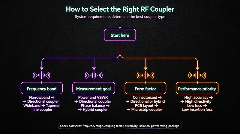
- Define the frequency range. Must cover your lowest and highest operating frequency, not just center.
- Choose coupling factor. Common defaults are 20 dB for monitoring and 3 dB for hybrids.
- Check directivity. Need > 25 dB for accurate power measurement in reflective loads.
- Determine topology. Directional, hybrid, Wilkinson, or bidirectional?
- Verify power handling. Include margin — 1.5× to 2× your peak power.
- Match connector type. SMA, N-Type, TNC, or 2.92 mm for millimeter-wave.
- Consider package style. Connectorized for lab use, surface-mount for production.
- Review environmental rating. Operating temperature, humidity, vibration, and altitude.
7. Common Pitfalls to Avoid
- Ignoring directivity near band edges. Always plot directivity across the full band.
- Unterminated isolated port. Always terminate with 50 Ω to avoid reflections and skewed measurements.
- Exceeding power rating. Peak power (not just average) can arc the internal traces.
- Mismatched impedance. 50 Ω coupler in a 75 Ω system causes VSWR spikes.
- Over-torque on connectors. Use a calibrated wrench (8 in-lbs for SMA).
- Confusing coupling with insertion loss. Coupling is intentional sampling; insertion loss is unwanted signal loss in the main path.
8. Frequently Asked Questions
Q1: What is the difference between a coupler and a power divider?
A coupler samples a small portion of the signal (e.g. 20 dB), passing most through. A power divider splits the signal more evenly, typically equally (3 dB) or into N equal portions.
Q2: What is a good directivity for an RF coupler?
For general-purpose monitoring, > 20 dB is acceptable. For precision measurement or low-reflection loads, > 30 dB is preferred.
Q3: Can I use a directional coupler as a combiner?
Yes, in many cases. Directional couplers are reciprocal — applying signals to the coupled and input ports combines them at the output port, with good isolation to the isolated port.
Q4: What frequency range do RF couplers cover?
From HF (using lumped elements) up to 110 GHz (using waveguide couplers). Most commercial RF and microwave couplers operate from 30 MHz to 40 GHz.
Q5: Why is the isolated port important?
The isolated port absorbs backward-traveling signals. If left unterminated, those signals reflect back into the coupler and corrupt measurements.
Q6: Are RF couplers passive?
Yes, all standard RF couplers are passive. They require no DC power and have no active components, which makes them extremely reliable.
9. Conclusion
RF couplers are versatile, passive building blocks that make modern wireless and microwave systems possible. Whether you need directional sampling for power monitoring, a 90° hybrid for I/Q modulation, or a Wilkinson divider for an antenna feed network, selecting the right coupler comes down to frequency range, coupling factor, directivity, power handling, and connector type. By following the selection checklist and avoiding the common pitfalls outlined above, you can ensure accurate, reliable signal routing across your entire RF system.
About the Author — MeiXun Team
Chief Engineer Wang
High-tech Enterprise, Feifeng Talent
Chief Engineer Wang graduated with a master's degree in high-power microwave from the Institute of Electronics, University of Chinese Academy of Sciences.
View Full Profile- RF Switch Circuit Diagram
- RF Switch
- Ohm's Law
- dBm to Watt
- mW to dBm
- Wavelength to Frequency
- RF Connector
- SMA Connector
- RF Switch Module
- RF Coupler
- RF PIN Switch
- Microwave Coaxial Switch
- PIN Switch
- Coaxial RF Switch
- Waveguide Switch
- Microwave Switch
- Low Noise Amplifier
- PIN Diode Switch
- Coaxial Switch
- RF Microwave Switch
- SPST Switch