


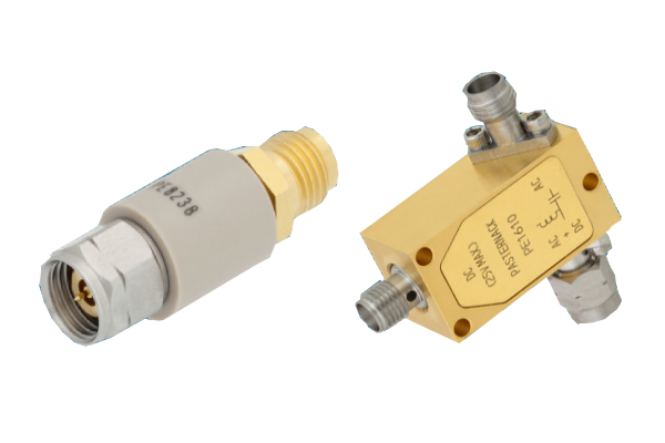
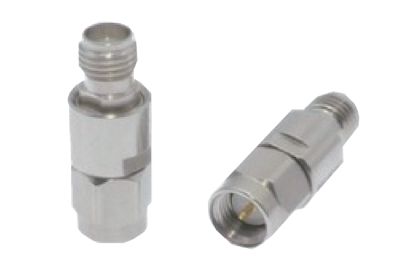
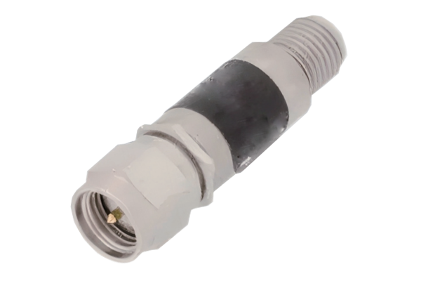
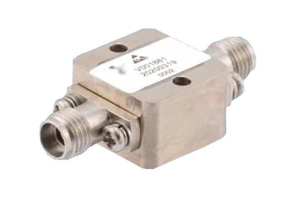
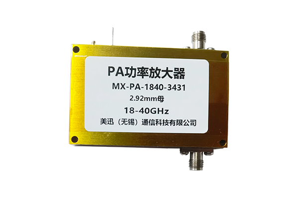
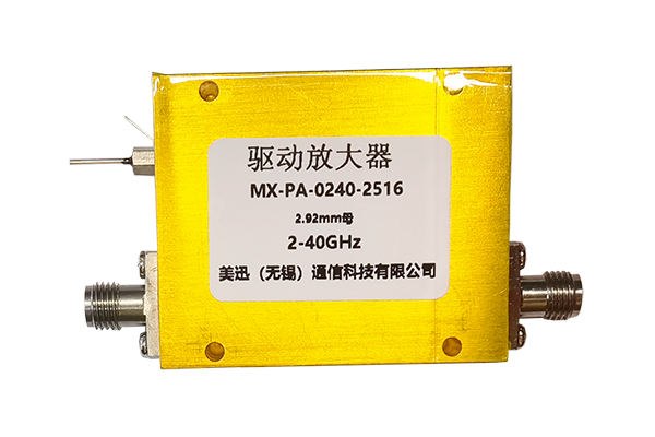




In modern RF and microwave systems, protecting sensitive receiver components from excessive input power is essential for maintaining system reliability and measurement accuracy. High-power RF signals, unexpected interference, transmitter leakage, and electromagnetic pulses can damage low-noise amplifiers (LNAs), mixers, and other sensitive receiver components.
An RF limiter is a critical protection component designed to restrict output power when the input signal exceeds a predetermined threshold. By limiting excessive RF energy, it helps prevent receiver damage while allowing low-level signals to pass with minimal attenuation.
This guide explains how RF limiters work, compares PIN diode limiters and high-power RF limiters, and provides a practical selection framework for receiver protection applications.
1. What Is an RF Limiter?
An RF limiter is a nonlinear microwave protection device that restricts the amplitude or power level of an incoming RF signal when it exceeds a specified threshold.
Under normal operating conditions, the limiter allows weak RF signals to pass with relatively low insertion loss. When the input power reaches a certain level, the limiting mechanism activates and reduces the amount of RF energy delivered to downstream components.
Typical components requiring protection include:
- Low Noise Amplifiers (LNAs)
- RF mixers and frequency converters
- Sensitive receiver front ends
- Microwave detectors
- Spectrum analyzer input stages
- Satellite communication receivers
- Radar signal processing circuits
How Does an RF Limiter Work?
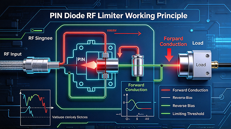
Most RF limiters operate by introducing a nonlinear impedance or signal attenuation mechanism when the input power exceeds a predefined threshold.
For example, a PIN diode limiter uses the power-dependent electrical characteristics of PIN diodes to change the impedance presented to the RF signal.
At low input power, the diode presents a relatively high impedance, allowing the signal to pass with low insertion loss. When a high-power RF signal arrives, the diode changes its conduction characteristics, creating a stronger attenuation path and reducing the transmitted signal level.
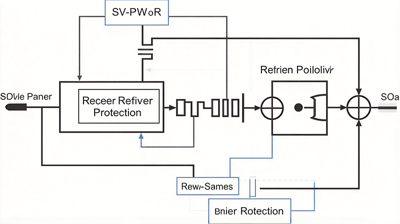
RF Input → RF Limiter → Low Noise Amplifier → Mixer → Signal Processing
The limiter is generally positioned before sensitive receiver components to reduce excessive input power.
2. Main Types of RF Limiters
RF limiters are available in several configurations, each offering different performance characteristics and protection capabilities.
2.1 PIN Diode Limiters
PIN diode limiters are among the most widely used solutions for RF and microwave receiver protection.
A PIN diode consists of three semiconductor regions: P-type, intrinsic, and N-type. Its RF impedance can be controlled by the stored charge within the intrinsic region.
Key Advantages:- Fast response to high-power RF signals
- Relatively low insertion loss
- Broadband design possibilities
- Compact circuit implementation
- Suitable for pulsed and CW applications within specified limits
2.2 Schottky Diode Limiters
Schottky diode limiters use the nonlinear characteristics of Schottky barrier diodes to provide RF signal limiting.
Key Advantages:- Fast switching characteristics
- Low junction capacitance in suitable devices
- Useful for high-frequency circuits
- Compact implementation
Their power-handling capability depends strongly on device construction and must be verified for the intended application.
2.3 High-Power RF Limiters
High-power RF limiters are designed to protect receiver circuits operating in environments with high incident RF power.
Key Advantages:- Higher RF input power tolerance
- Protection under strong interference conditions
- Suitable for demanding transmitter-receiver environments
- Engineered for high peak-power applications
2.4 Passive RF Limiters
Passive RF limiters operate without requiring an external power supply for their limiting function.
Key Advantages:- No external DC power required for limiting
- Simple system integration
- Low power consumption
- Useful in compact microwave systems
3. PIN Diode Limiter vs. High Power RF Limiter
PIN diode limiters and high-power RF limiters are not necessarily mutually exclusive categories. Many high-power limiters also use PIN diode technology. The distinction is primarily based on design objectives and power-handling requirements.
| Performance Parameter | Conventional PIN Diode Limiter | High-Power RF Limiter |
|---|---|---|
| Main Purpose | RF signal limiting | Protection under high RF power |
| Input Power Handling | Design-dependent | Optimized for higher power |
| Insertion Loss | Designed to be low | Depends on power-handling architecture |
| Limiting Capability | Depends on diode configuration | Designed for demanding input conditions |
| Thermal Management | Application-dependent | Often more critical |
| Typical Applications | RF receivers and communications | Radar, EW, high-power systems |
| Design Complexity | Low to high | Often higher |
Which One Should You Choose?
Choose a conventional PIN diode limiter when the application requires low insertion loss, fast response, and effective protection against moderate RF power levels.
Choose a high-power RF limiter when the system is exposed to strong transmitter leakage, high-power interference, intense RF pulses, or other demanding input conditions.
The final selection should always be based on measured or specified operating requirements.
4. Key RF Limiter Specifications to Consider
Selecting an RF limiter requires a comprehensive evaluation of its electrical and environmental characteristics.
4.1 Operating Frequency Range
The operating frequency range defines the frequencies over which the limiter meets its specified performance.
Engineers should verify minimum and maximum operating frequencies, insertion loss across the band, limiting performance, and return loss or VSWR.
4.2 Insertion Loss
Insertion loss measures the reduction in signal power when the limiter operates under normal low-power conditions. It is usually expressed in decibels (dB).
A lower insertion loss is generally preferred, particularly in sensitive receiver front ends. Excessive insertion loss can reduce the signal level reaching the LNA and negatively affect receiver noise performance.
4.3 Limiting Threshold
The limiting threshold is the input power level at which the limiter begins to provide significant attenuation.
If the threshold is too high, downstream components may be exposed to damaging power before effective limiting occurs. If it is too low, normal signals may be unnecessarily attenuated.
4.4 Flat Leakage Power
Flat leakage power describes the approximate output power level reached under sufficiently strong input conditions after the limiter enters its limiting region.
A lower leakage level generally provides better protection, but the actual acceptable value depends on the maximum safe input power of the downstream component.
4.5 Recovery Time
Recovery time describes how quickly the limiter returns to its normal low-loss operating condition after a high-power signal disappears or decreases.
This parameter is particularly important in pulsed radar and time-sensitive communication systems.
4.6 Maximum Input Power
Engineers should distinguish between:
- Maximum continuous-wave (CW) input power
- Maximum peak pulse power
- Maximum average power
- Maximum energy per pulse
These parameters are not interchangeable. A limiter capable of handling a high peak power for a very short pulse may not withstand the same power continuously.
4.7 VSWR and Return Loss
Voltage Standing Wave Ratio (VSWR) and return loss describe impedance matching performance. Poor matching can cause signal reflections, reduce transmission efficiency, and affect connected RF components.
5. How to Select an RF Limiter for Receiver Protection
A systematic selection process helps ensure that the limiter provides adequate protection without unnecessarily degrading receiver sensitivity.
Identify the Receiver's Maximum Safe Input Power
Determine the maximum allowable input power of the component being protected. The selected limiter must keep the delivered power within that component's safe operating range.
Determine the Maximum Expected RF Input Power
Identify the strongest possible signal that may reach the receiver, including transmitter leakage, nearby RF sources, intentional interference, and radar pulse coupling.
Select the Appropriate Limiting Threshold
The threshold must be high enough to avoid interfering with normal signal reception but low enough to provide timely protection.
Evaluate Insertion Loss and Noise Performance
For a passive matched limiter before the first amplifier, insertion loss approximately adds directly to the receiver noise figure in decibels at standard reference temperature.
Verify Pulse Handling and Recovery Performance
For radar and pulsed RF systems, evaluate peak input power, pulse duration, pulse repetition frequency, duty cycle, and recovery time.
Consider Environmental and Mechanical Requirements
Check operating temperature, humidity, vibration, shock resistance, connector type, package dimensions, and impedance requirements.
6. RF Limiter Applications in Modern Microwave Systems
6.1 Radar Receiver Protection
Radar systems often use high-power transmitters and sensitive receivers that share an antenna or operate in close proximity. During transmission, significant RF energy may enter the receiver path through antenna coupling, circulators, or other RF components.
An RF limiter helps reduce the power reaching sensitive receiver components. Fast recovery is particularly important in pulsed radar systems because the receiver must return to normal operation quickly after each transmission event.
6.2 Electronic Warfare Systems
Electronic warfare systems operate in complex electromagnetic environments with potentially strong interference and high-power signals. RF limiters help protect sensitive receiver front ends while maintaining the ability to detect weak signals.
6.3 Satellite Communication Systems
Satellite communication receivers must detect extremely weak signals. Excessive RF power from nearby transmitters or other sources can overload or damage sensitive receiver components. Low insertion loss and effective limiting performance are particularly important.
6.4 Wireless Communication Infrastructure
In wireless base stations and RF communication infrastructure, receiver circuits may be exposed to strong adjacent-channel signals, transmitter leakage, or external interference. RF limiters can help improve front-end robustness.
6.5 RF and Microwave Test Equipment
Spectrum analyzers, vector network analyzers, and other RF measurement instruments may have sensitive input stages. External RF limiters can provide additional protection when testing unknown or potentially high-power signals.
7. Common RF Limiter Selection Mistakes
Mistake 1: Selecting Based Only on Maximum Input Power
Maximum input power does not fully describe protection performance. Limiting threshold, flat leakage, pulse energy, and recovery time must also be evaluated.
Mistake 2: Ignoring Insertion Loss
High insertion loss can degrade receiver sensitivity, especially when the limiter is installed before an LNA.
Mistake 3: Confusing Peak Power with Average Power
Peak and average power describe different aspects of RF energy. A limiter must be evaluated against the actual waveform and duty cycle.
Mistake 4: Ignoring Recovery Time
A limiter that recovers too slowly may prevent the system from detecting weak signals immediately after a strong pulse.
Mistake 5: Overlooking Frequency-Dependent Performance
Insertion loss, return loss, and limiting characteristics can vary significantly across the frequency band. Always evaluate the full operating bandwidth.
8. RF Limiter Selection Checklist
Before purchasing or integrating an RF limiter, engineers should confirm the following parameters.
| Selection Parameter | Key Question |
|---|---|
| Frequency Range | Does it cover the entire operating band? |
| Impedance | Is it compatible with the system impedance? |
| Insertion Loss | Is normal signal attenuation sufficiently low? |
| Limiting Threshold | Does limiting begin at the appropriate input level? |
| Flat Leakage | Is the output safe for the downstream receiver? |
| Recovery Time | Can the limiter recover within the required time? |
| Peak Power | Can it withstand the maximum input pulse? |
| Average Power | Can it handle continuous thermal loading? |
| VSWR | Is impedance matching acceptable? |
| Environment | Does it meet temperature and mechanical requirements? |
9. Frequently Asked Questions About RF Limiters
Q1: What is the main purpose of an RF limiter?
The primary purpose of an RF limiter is to protect sensitive RF and microwave receiver components from excessive input power by reducing signal transmission when the input exceeds a specified threshold.
Q2: What is a PIN diode RF limiter?
A PIN diode RF limiter is a nonlinear protection device that uses the electrical characteristics of PIN diodes to attenuate high-power RF signals while allowing lower-power signals to pass with relatively low insertion loss.
Q3: What is the difference between an RF limiter and an RF attenuator?
An RF attenuator provides a specified amount of signal attenuation, generally independent of input power within its operating range. An RF limiter provides power-dependent attenuation and increases attenuation when the input power exceeds a designed threshold.
Q4: Can an RF limiter protect an LNA?
Yes. RF limiters are frequently installed before low-noise amplifiers to reduce excessive input power and help prevent LNA damage. Protection effectiveness depends on limiting threshold, leakage power, response time, and the LNA's maximum safe input rating.
Q5: What is the difference between peak power and average power?
Peak power represents the maximum instantaneous power of an RF signal, while average power represents power averaged over time. Peak power is particularly important for pulsed radar signals, whereas average power is critical for evaluating thermal loading.
Q6: Are PIN diode limiters suitable for high-power applications?
They can be. PIN diode technology is used in many high-power limiter designs. However, actual power-handling capability depends on diode construction, circuit topology, thermal design, pulse conditions, and packaging.
Q7: Does an RF limiter affect receiver sensitivity?
Yes. An RF limiter introduces insertion loss under normal signal conditions. When installed before the first low-noise amplifier, this loss approximately increases the receiver noise figure by the same amount in decibels for a passive matched component at standard reference temperature.
10. Conclusion: Choosing the Right RF Limiter for Reliable Receiver Protection
Selecting the right RF limiter requires balancing receiver sensitivity, input power handling, limiting performance, and recovery characteristics.
PIN diode limiters provide an effective solution for many RF and microwave receiver protection applications, while high-power limiter designs are better suited to demanding environments involving strong RF signals and high-energy pulses.
The most important selection criteria include:
- Operating frequency range
- Insertion loss
- Limiting threshold
- Flat leakage power
- Recovery time
- Peak and average input power
- VSWR and environmental requirements
By evaluating these parameters together, engineers can select an RF limiter that provides reliable protection without compromising normal receiver performance.
Explore RF and Microwave Component Solutions
Looking for reliable RF and microwave components for your next project? Visit MeiXun to explore RF component solutions and discuss your application requirements with our engineering team.
Visit MeiXun Website