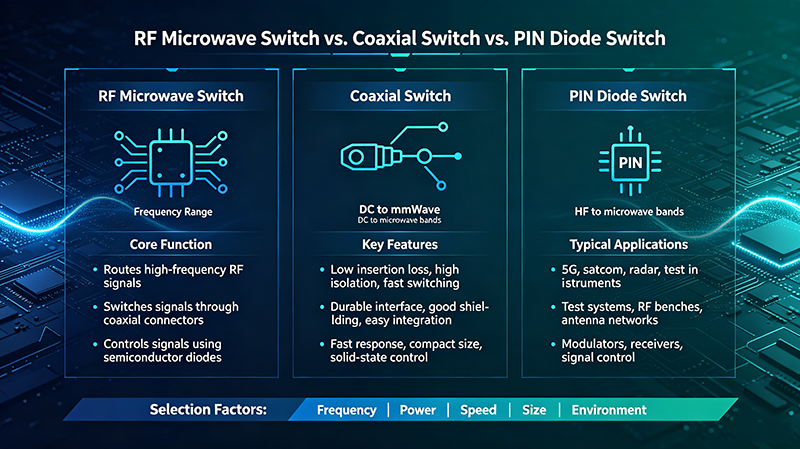
A PIN diode switch is a solid-state RF switch that uses PIN diodes to control signal routing in microwave and RF circuits. Known for fast switching speeds, high reliability, and excellent RF performance, PIN diode switches are widely used in telecommunications, radar systems, and test equipment.
What Is a PIN Diode Switch?
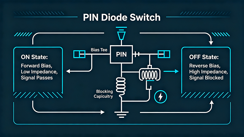
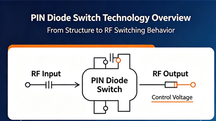
A PIN diode switch is an electronic switching device that employs PIN (Positive-Intrinsic-Negative) diodes to control the routing of radio frequency and microwave signals. Unlike mechanical switches, PIN diode switches operate entirely through semiconductor behavior, offering superior switching speeds and virtually unlimited operational life.
The PIN diode switch is a type of solid-state switch, meaning it has no moving parts. This makes it ideal for applications requiring high reliability, fast switching, and silent operation. The switch can route signals between multiple paths by controlling the bias voltage applied to the PIN diodes.
How Does a PIN Diode Switch Work?
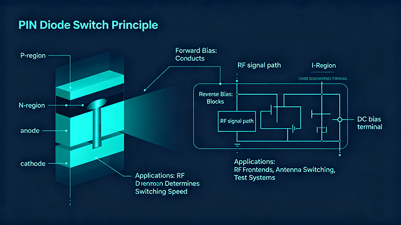
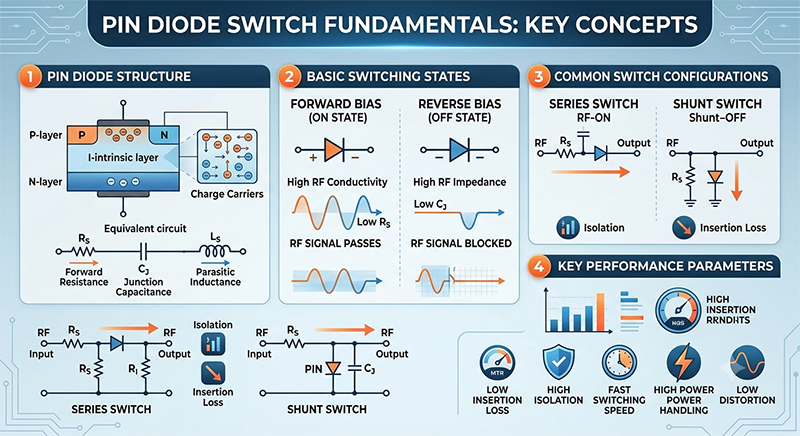
PIN diode switches operate based on the unique electrical characteristics of PIN diodes. A PIN diode consists of three layers:
- P-type layer: Contains positive charge carriers (holes)
- Intrinsic (I) layer: An undoped semiconductor region
- N-type layer: Contains negative charge carriers (electrons)
PIN Diode Structure: P-I-N Configuration
The intrinsic region allows the diode to behave differently from a standard diode at high frequencies.
Forward Bias Operation
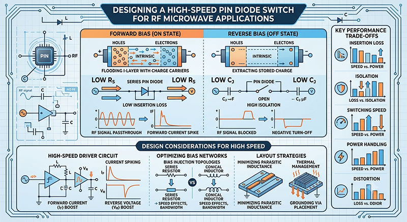
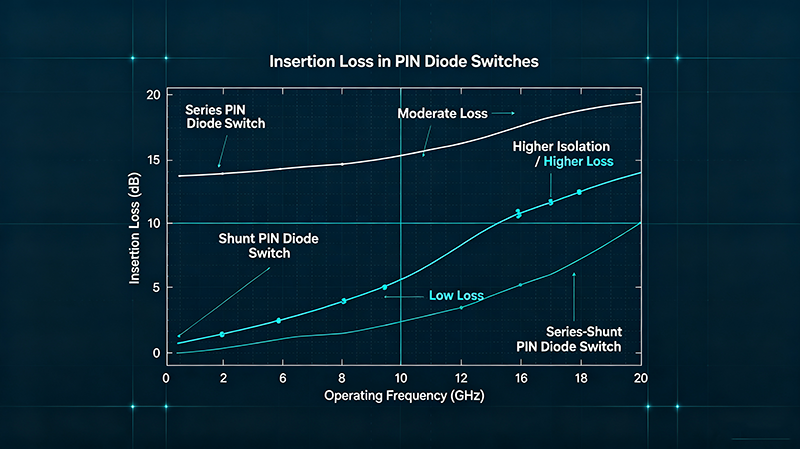
When forward-biased (positive voltage applied), the PIN diode presents a low resistance, typically 0.5 to 5 ohms. In this state, the diode acts as a closed switch, allowing RF signals to pass through with minimal insertion loss.
Reverse Bias Operation
When reverse-biased, the PIN diode presents a high resistance, typically hundreds of ohms. The intrinsic region acts as an insulating barrier, blocking RF signal passage. This state creates an open switch with high isolation between ports.
Switching Control
The switch circuit typically uses multiple PIN diodes configured to create series and shunt switching elements. By applying appropriate bias voltages to each diode, the circuit routes signals to the desired output port.
Types of PIN Diode Switches
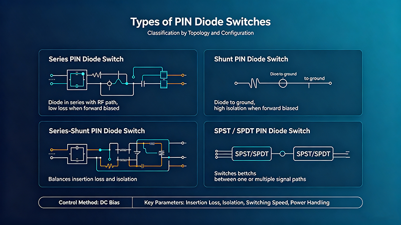
The most common configuration. Routes one input to one of two outputs. Used for signal routing, redundancy switching, and toggle applications. Perfect for basic switching needs in test equipment and communication systems.
Single Pole Triple or Quad Throw switches provide three or four output options from one input. Essential for complex signal distribution networks and multi-channel switching systems.
Connects one input between two outputs with make-before-break operation. Used for signal monitoring and backup routing applications where continuous signal path is critical.
Complex switching networks that provide multiple input and output connections. Allows flexible signal routing in automated test systems and communication networks.
Key Specifications
| Parameter | Specification | Notes |
|---|---|---|
| Frequency Range | 100 MHz to 50 GHz | Varies by design |
| Insertion Loss | 0.2 dB to 2.0 dB | Lower is better |
| Isolation | 30 dB to 70 dB | Higher is better |
| VSWR | 1.15:1 to 1.5:1 | Closer to 1:1 is better |
| Switching Speed | 10 ns to 1 µs | Fast response time |
| Control Voltage | +5V, +12V, +28V | Industry standard |
Key Advantages
Applications
PIN diode switches are used across a wide range of RF and microwave applications:
Telecommunications
In cellular base stations and mobile networks, PIN diode switches enable antenna selection, signal routing, and redundancy switching. Their fast switching capability supports time-division duplexing and frequency hopping systems.
Radar Systems
Radar applications require switches that can handle high power pulses and switch rapidly. PIN diode switches are used for transmit/receive switching, antenna beam steering, and signal routing in both civilian and military radar systems.
Test and Measurement
Automated test equipment uses PIN diode switches to route signals between multiple devices under test and measurement instruments. The fast switching speed increases test throughput while the high reliability ensures long-term performance.
PIN Diode vs. Other RF Switches
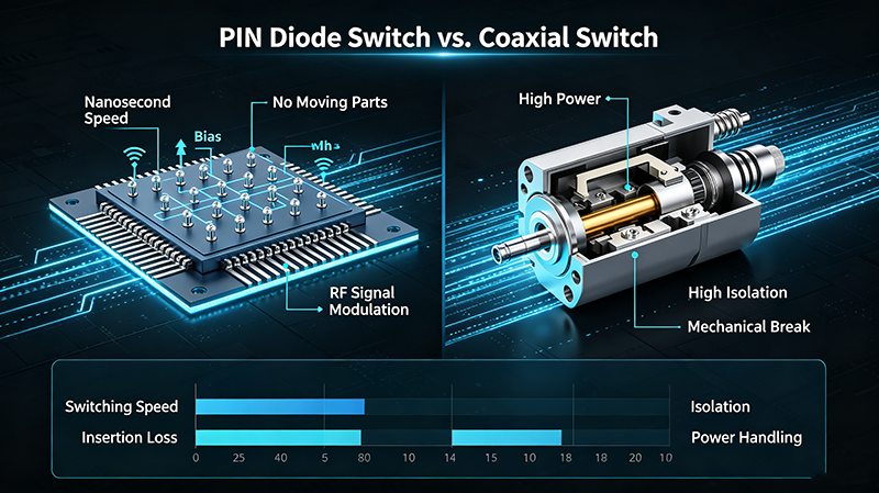
| Feature | PIN Diode Switch | Electromechanical |
|---|---|---|
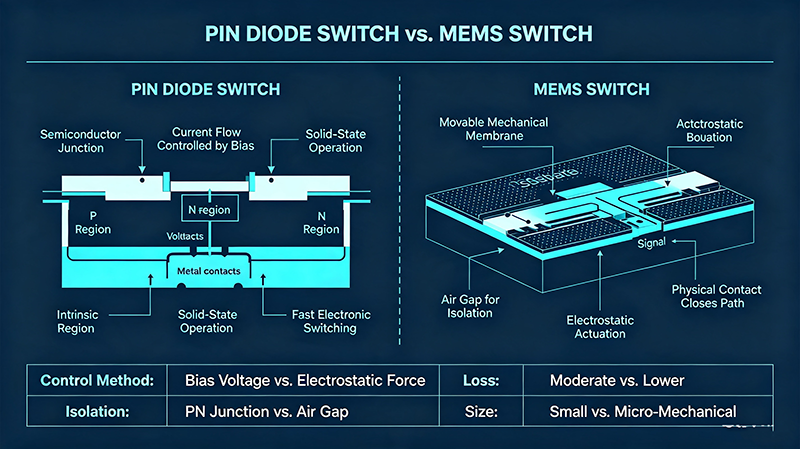
| Switching Speed | 10 ns - 1 µs | 5 ms - 50 ms |
| Life Cycles | 10^10 operations | 10^6 operations |
| Insertion Loss | 0.3 dB - 1.5 dB | 0.1 dB - 0.5 dB |
| Isolation | 30 dB - 70 dB | 60 dB - 100 dB |
| Power Handling | Up to 100W | Up to 1000W |
| Cost | Moderate | Lower for basic |
How to Select the Right PIN Diode Switch
Consider these key factors when choosing a PIN diode switch:
- Frequency Range: Ensure the switch covers your entire operating band with acceptable performance
- Insertion Loss: Evaluate the signal loss budget and its impact on system performance
- Isolation Requirements: Higher isolation reduces cross-talk in multi-channel systems
- Switching Speed: Match the speed to your application timing requirements
- Power Handling: Verify both peak and average power specifications meet your needs
- Control Interface: Consider TTL/CMOS compatibility and drive circuit requirements
- Package Type: Choose between connectorized, surface mount, or drop-in configurations
Frequently Asked Questions
Summary
PIN diode switches are essential solid-state components for modern RF and microwave systems. They offer an excellent combination of switching speed, reliability, and RF performance. Understanding their operating principles, specifications, and applications will help you select the right switch for your design requirements.
Need a PIN Diode Switch for Your Project?
Our engineering team can help you select the optimal switch for your specific application.
Contact Technical Sales