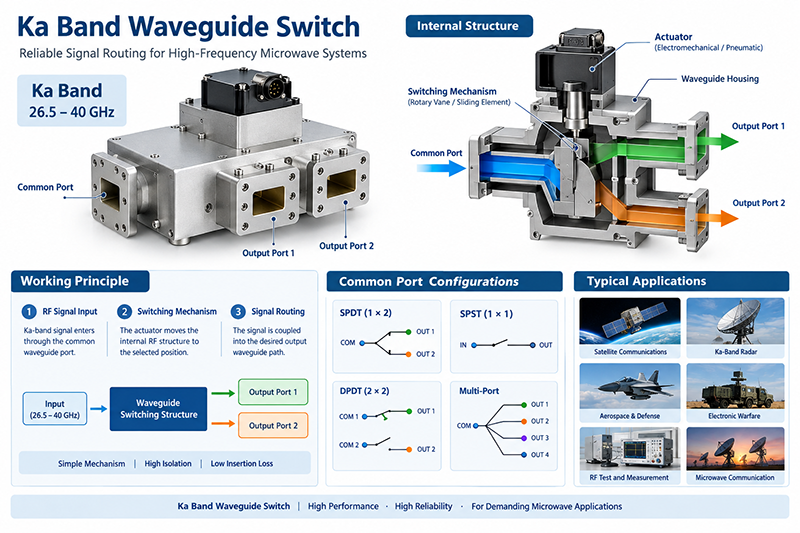
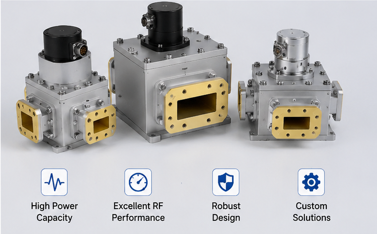
1. What Is a Waveguide Switch?
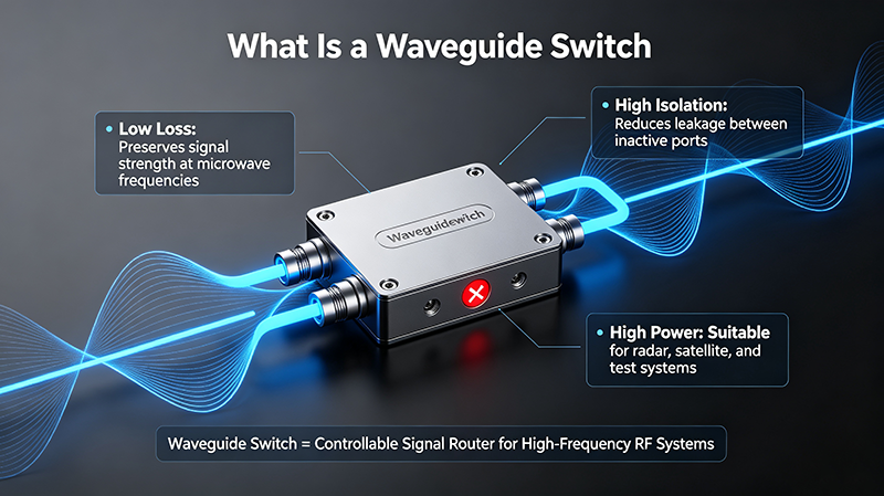
A Waveguide Switch is a passive or electromechanical RF component engineered to route high-frequency microwave and millimeter-wave signals between multiple waveguide transmission lines. Unlike coaxial switches limited by low power handling capacity, a standard waveguide switch delivers exceptional power transmission performance at frequencies ranging from 1 GHz to over 110 GHz, making it irreplaceable for high-power RF test benches, radar equipment, satellite communication hardware, and aerospace radio frequency subsystems.
The core mechanical structure of a waveguide switch contains precision metal waveguide cavities, internal rotating or sliding short-circuit plungers, electromagnetic drive actuators, and control signal interfaces. When receiving DC control voltage signals, the actuator adjusts the internal conductive component position, blocking or opening specific waveguide signal channels to realize controllable signal switching without signal cross-talk under rated working power.
2. Core Working Principle of Waveguide Switch
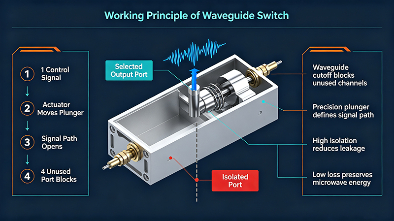
All waveguide switch models operate based on the cutoff characteristic of rectangular or circular waveguide transmission media. Microwave signals can only propagate along designated waveguide channels; metal conductors inside the waveguide switch block electromagnetic wave propagation when aligned with a channel, and restore signal transmission when retracted.
Electromechanical Waveguide Switch Operation Flow
- 1. External controller transmits 12V/24V DC drive signal to the waveguide switch electromagnetic coil
- 2. The coil generates magnetic force to push the internal mechanical linkage and metal shorting bar
- 3. The shorting bar blocks unused waveguide ports while clearing the target signal transmission channel
- 4. Built-in position feedback sensors send channel state signals back to the test control system for real-time monitoring
High-end high-power waveguide switches add cooling grooves and silver-plated inner cavity surfaces to reduce insertion loss and prevent thermal deformation under continuous high-power signal loads, which effectively extends the service life of the waveguide switch in long-duration test applications.
3. Main Classifications of Waveguide Switch
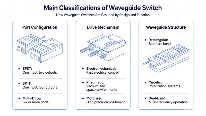
Waveguide switch products are categorized by port count, drive mode, waveguide shape, and power rating. Below are the most widely adopted types in global RF industries:
3.1 By Port Configuration
- Single-pole double-throw (SPDT) Waveguide Switch: The most mainstream type, 1 input port + 2 output ports for two-way signal switching
- Single-pole four-throw (SP4T) Waveguide Switch: Four-channel signal routing for multi-device automated test systems
- Multi-throw Custom Waveguide Switch: SP6T, SP8T and above for large-scale radar array calibration platforms
3.2 By Drive Mechanism
- Electromechanical Waveguide Switch: Low insertion loss, high isolation, suitable for continuous wave high-power signals, mainstream industrial choice
- Pneumatic Waveguide Switch: Ideal for vacuum aerospace environments without electric spark risks, deployed on satellite payloads
- Motorized Waveguide Switch: Slow switching speed but ultra-high precision positioning for laboratory calibration equipment
3.3 By Waveguide Structure
Rectangular waveguide switch covers most common frequency bands including X-band, Ku-band, Ka-band and W-band. Circular waveguide switch is used for circular polarization radar and millimeter-wave satellite communication systems due to symmetric signal transmission characteristics.
4. Critical Performance Specifications of Waveguide Switch
When selecting a waveguide switch for engineering projects, engineers must evaluate these key electrical parameters to match system frequency and power requirements:
| Parameter | Definition & Standard Requirement |
|---|---|
| Operating Frequency Band | Covers WR-10 to WR-90 waveguide bands, customized broadband waveguide switch available |
| Insertion Loss | Typically ≤0.3dB for X-band waveguide switch; lower loss ensures minimal signal attenuation |
| Isolation | ≥60dB between isolated ports to eliminate signal leakage and cross interference |
| Power Handling | CW power up to 10kW, peak pulse power over 100kW for high-power radar waveguide switch |
| Switching Time | Standard electromechanical waveguide switch: 10ms to 50ms switching response |
| VSWR | Maximum VSWR ≤1.2:1 to avoid signal reflection damage to signal sources |
5. Primary Application Fields of Waveguide Switch
The high power and low loss advantages of waveguide switch make it essential hardware across military, aerospace, telecom and test measurement sectors:
- Radar Detection Systems: Phased array radar, weather radar, airborne radar channel signal routing using Ka-band waveguide switch
- Satellite & Space Communication: Pneumatic waveguide switch installed on satellite transponders for space-grade signal switching
- 5G & Millimeter-Wave Base Station Test: Automated production test lines rely on SPDT waveguide switch for mass device calibration
- RF Microwave Test Benches: Laboratory vector network analyzer matching multi-channel waveguide switch for component testing
- Electronic Warfare Equipment: High isolation waveguide switch for signal shielding and channel switching in EW receivers
- Medical Accelerator Equipment: High-power waveguide switch controlling microwave signal transmission in particle accelerators
6. Waveguide Switch Selection Guide for Engineers
Improper waveguide switch selection will cause signal loss, power breakdown or system failure. Follow these core selection criteria:
First, confirm the operating frequency band and corresponding WR waveguide size; mismatched waveguide dimensions will generate severe signal reflection. Second, calculate the maximum continuous wave and peak pulse power of your system to select a waveguide switch with sufficient power margin, at least 30% higher rated power than actual working power.
Third, check isolation and insertion loss indicators. Test and measurement scenarios demand isolation above 70dB, while general communication equipment accepts 50dB-60dB isolation. Fourth, select the drive type: electromechanical waveguide switch for ground equipment, pneumatic models for vacuum space environments.
Looking for customized high-performance waveguide switch for your radar, satellite or RF test system? Contact professional waveguide component manufacturers to get tailored frequency band, port count and power rating waveguide switch solutions with full technical datasheets.