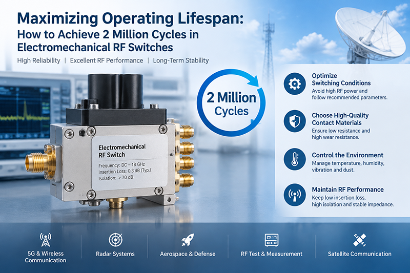
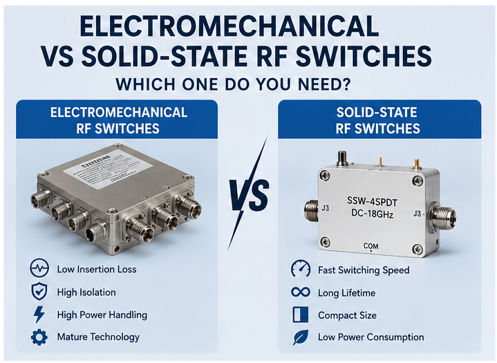
Electromechanical RF switches — coaxial relays,
waveguide switches, transfer switches — are reliable workhorses of test, broadcast, and defense systems. With proper handling, an
RF switch rated for 1 million cycles can deliver 5 – 10 million cycles or more. With poor handling, even 100,000-cycle-rated switches fail early.
Quick Answer
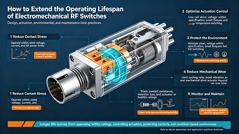
The lifespan of an electromechanical RF switch is dominated by contact wear and arcing. To maximize life: cold-switch whenever possible (turn off RF before switching), derate power by 50 % or more, control temperature, match loads to minimize VSWR, use latching drivers for low-power states, and follow a preventive maintenance schedule. These practices can extend life by 5× – 10×.
What Limits Switch Life?
Electromechanical RF switches fail primarily from three mechanisms:
-
Contact wear: every actuation creates a small arc that erodes the gold or silver-plated contacts. Over millions of cycles, contact resistance rises and insertion loss drifts upward.
-
Contact welding: a sustained arc fuses contacts together; the switch becomes stuck in one position.
-
Mechanical wear: the actuator, detent, and bearings degrade after repeated operation.
The dominant failure mode depends on the application. Hot-switched high-power systems fail first from welding; cold-switched systems fail from mechanical wear over millions of cycles.
Life Ratings Explained
|
Switch Type
|
Typical Life (cycles)
|
Failure Mode
|
|
Standard coaxial relay
|
1M – 5M
|
Contact wear
|
|
High-end coaxial relay
|
5M – 10M
|
Contact wear
|
|
Latching coaxial
|
5M – 20M
|
Mechanical wear
|
|
Waveguide switch
|
1M – 5M
|
Mechanical wear
|
|
High-power coaxial
|
100k – 1M
|
Contact welding
|
Cold Switching
-
RF power is OFF when contacts move.
-
No arc forms; contact wear is mechanical only.
-
Extends life by 10× – 100×.
-
Default choice for ATE and instrumentation.
Hot Switching
-
RF power is ON when contacts move.
-
Arc forms at every transition; heavy contact wear.
-
Drastically reduces life.
-
Required only when system timing cannot pause RF.
Rule of Thumb: Cold switching can extend a switch's life from 100,000 hot-switched cycles to 5 – 10 million cold-switched cycles. Whenever timing allows, switch off the RF source before transitioning the switch.
Practical Lifespan Strategies
1. Cold Switch Whenever Possible
Disable the RF source before commanding the switch. Use a sequencing controller to enforce this rule.
2. Derate Power
Run at 50 % of the rated hot-switched power. Arc energy scales with voltage and current, so even small reductions help.
3. Control Temperature
Each 10 °C reduction in ambient temperature approximately doubles life. Mount switches on metal chassis or heat sinks; ensure airflow in confined enclosures.
4. Match Loads Properly
VSWR > 1.5:1 reflects power back into the switch, multiplying voltage and current stress. Use precision terminations and well-matched antennas.
5. Use Latching Relays for Idle States
Latching switches hold position with no current. They are ideal for systems that spend most of their time in one state, dramatically reducing continuous power dissipation and contact cycling.
6. Add Redundant Paths
Critical systems should include a bypass switch that takes over when the primary fails. This prevents whole-system outages from a single switch failure.
7. Slow Down Switching When Possible
Avoid unnecessary switching. If a port is connected for a long measurement, hold the position rather than toggling.
8. Monitor Contact Resistance
Track insertion loss or contact resistance over time. A slow increase is the first sign of contact wear and can trigger scheduled replacement before failure.
Switch Lifecycle Best Practices
1. Use a Sequencing Controller
Implement a controller that ensures RF is OFF before switch transitions and ON only after settling time.
2. Soft-Start Transients
Bring RF up gradually after switching to avoid overshoot that could exceed the hot-switch rating.
3. Monitor Cycle Count
Use a counter to track actuations. Replace the switch at 75 – 80 % of rated life for predictable maintenance.
4. Clean Connectors Regularly
Dirt and oxidation on RF connectors raise loss and generate arcs. Clean and torque connectors at intervals.
5. Verify with Calibration
Include the switch in regular calibration cycles. Drift indicates wear before catastrophic failure.
6. Avoid Hot-Switching Under Load Mismatch
Hot switching with VSWR > 2:1 causes extreme arc energy. Always match the load or use cold switching.
7. Limit Actuation Rate
Allow settling time (typically 10 – 30 ms for coaxial) before enabling RF. Rapid cycling creates contact bounce and stress.
8. Use the Right Driver
Match the driver voltage and current to the switch coil. Overdrive accelerates mechanical wear; underdrive causes sluggish actuation and contact bounce.
Operating-Class Impact
|
Operating Condition
|
Effect on Life
|
|
Cold switching
|
Mechanical wear only; 5 – 10M+ cycles
|
|
Hot switching at 25 % power
|
Moderate arcing; 1 – 2M cycles
|
|
Hot switching at 50 % power
|
Heavy arcing; 200k – 500k cycles
|
|
Hot switching at full power
|
Severe arcing; 50k – 200k cycles
|
|
Hot switching under VSWR > 2:1
|
Catastrophic; 10k – 100k cycles
|
Environmental Factors
-
Temperature: hot environments accelerate contact oxidation and lubricant degradation.
-
Humidity: moisture can corrode contacts and reduce insulation resistance.
-
Vibration: mechanical shock can cause unintended switching or contact bounce.
-
Dust: particulate contamination can prevent proper contact engagement.
-
Altitude: lower air pressure reduces dielectric strength, lowering peak power rating.
Preventive Maintenance Checklist
-
Measure insertion loss and VSWR every 100,000 cycles.
-
Clean RF connectors with isopropyl alcohol and a lint-free swab.
-
Torque connectors to the manufacturer's specification.
-
Inspect cables for kinks, cracks, or damaged shielding.
-
Verify driver voltage and current at the switch coil.
-
Confirm ambient temperature is within the switch's rated range.
-
Replace the switch at 75 – 80 % of rated life for critical applications.
Warning Signs of Wear
-
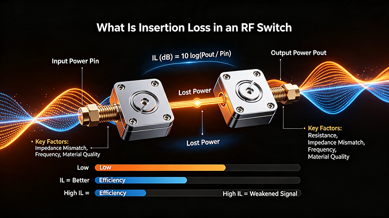
Insertion loss increases by > 0.2 dB from initial value.
-
VSWR degrades from < 1.2:1 to > 1.5:1.
-
Switch occasionally fails to actuate (intermittent connection).
-
Audible change in actuation sound — sluggish or "soft" engagement.
-
Visible pitting or discoloration on accessible contacts.
Common Mistakes
-
Hot-switching when cold-switching is possible: the most common cause of premature failure.
-
Ignoring VSWR: mismatched loads double or triple the arc energy.
-
Exceeding coil voltage: over-driving the actuator accelerates mechanical wear.
-
Insufficient settling time: switching while contacts bounce creates repeated strikes.
-
Dirty connectors: contamination raises contact resistance and accelerates wear.
Real-World Examples
Cellular ATE Test Bench
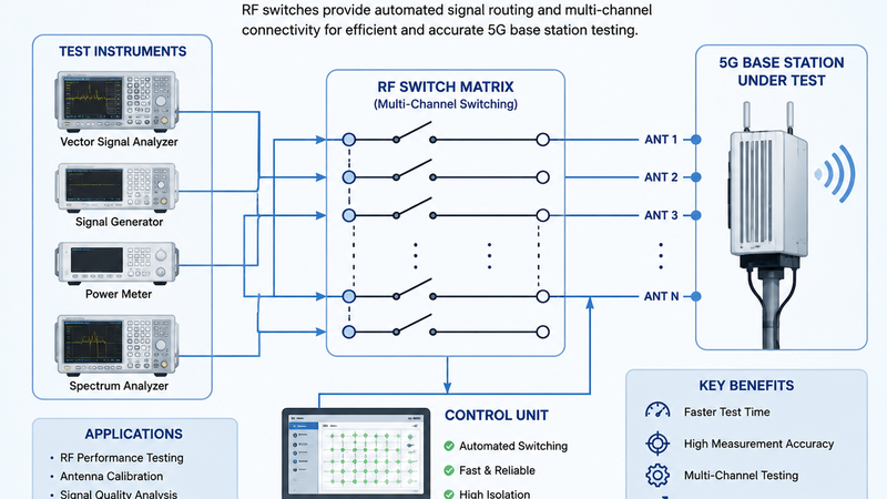
Coaxial switches cycle hundreds of times per test. Cold-switched, properly derated, with periodic cleaning — these benches run for 5+ years without switch replacement.
Broadcast Transmitter
Coaxial switches route between main and backup transmitters. Hot-switched but rarely; latching relays hold the state; these switches last decades.
Radar Front-End
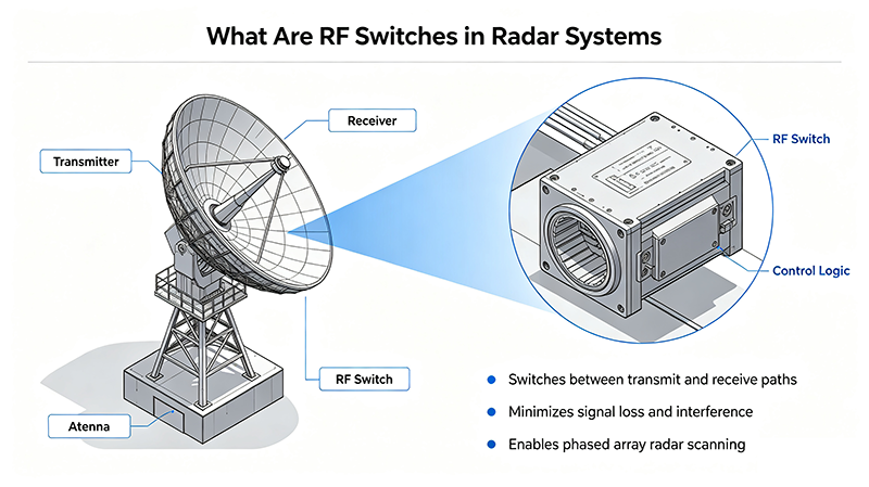
Waveguide switches route between transmit and receive paths. Hot-switched with high peak power but very low duty cycle — life is dominated by arcing, not wear. Cold-switching where possible extends life 5×.
Key Takeaways
-
Cold switching is the single most effective way to extend switch life.
-
Derate power by 50 % or more for reliability.
-
Control temperature and humidity; each 10 °C drop roughly doubles life.
-
Match loads to keep VSWR below 1.5:1.
-
Monitor insertion loss and cycle count to plan preventive replacement.
Frequently Asked Questions
What is the single most important way to extend switch life?
Cold-switching — turning off the RF source before transitioning the switch. Cold-switched switches can last 10× – 100× longer than hot-switched equivalents.
Does derating actually help?
Yes. Arc energy is proportional to voltage and current, so even a 30 % power reduction dramatically reduces contact wear.
How do I know when to replace a switch?
Track cycle count and measure insertion loss / VSWR regularly. Replace at 75 – 80 % of rated life or when performance degrades.
Are latching relays better for life?
Yes, if the switch spends most of its time in one position. Latching relays consume no holding current and experience no contact cycling while idle.
Can I clean worn contacts?
Generally no. Once contacts show pitting or oxidation, replacement is the only reliable option. Cleaning accessible connectors is fine, but internal contacts cannot be restored.