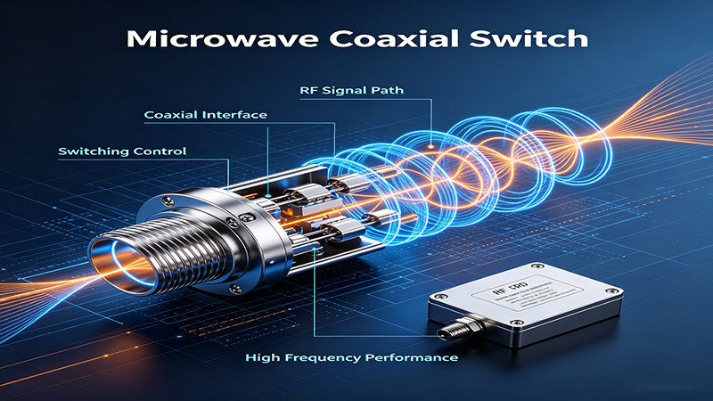
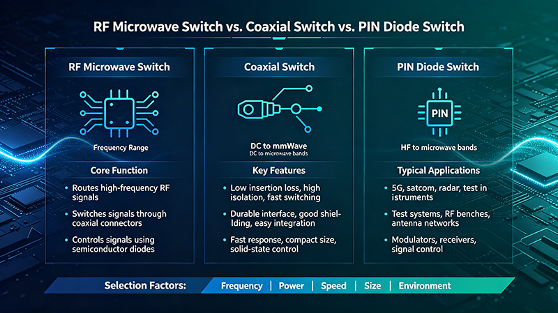
A coaxial switch is a precision electromechanical or solid-state device that routes radio-frequency (RF) and microwave signals between multiple coaxial transmission paths. As the backbone of RF signal routing, it is essential to test equipment, communication systems, radar, aerospace and 5G/6G infrastructure. This complete guide covers how coaxial switches work, every common configuration, the specifications that drive performance, how to compare them against other coaxial RF switches, and how to select the right one — including high-frequency up to 67 GHz solutions.
Table of Contents
- What Is a Coaxial Switch?
- How Does a Coaxial Switch Work?
- Main Types of Coaxial Switches
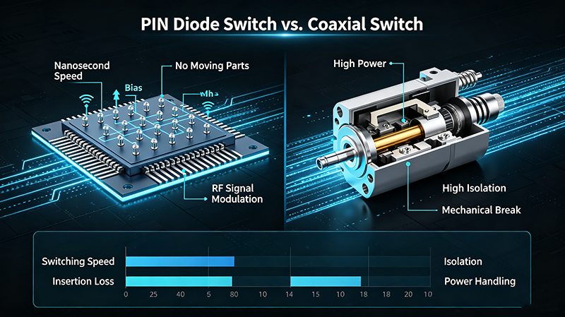
- Electromechanical vs. Solid-State RF Switches
- Key Coaxial Switch Specifications
- Coaxial Switch vs. Other RF Switch Technologies
- Coaxial Switch Applications
- How to Select a Coaxial Switch
- High-Frequency Coaxial Switches (Up to 67 GHz)
- Coaxial Switch Frequency Ranges
- Common Coaxial Switch Configurations
- Coaxial Switch FAQs
- Conclusion
What Is a Coaxial Switch?
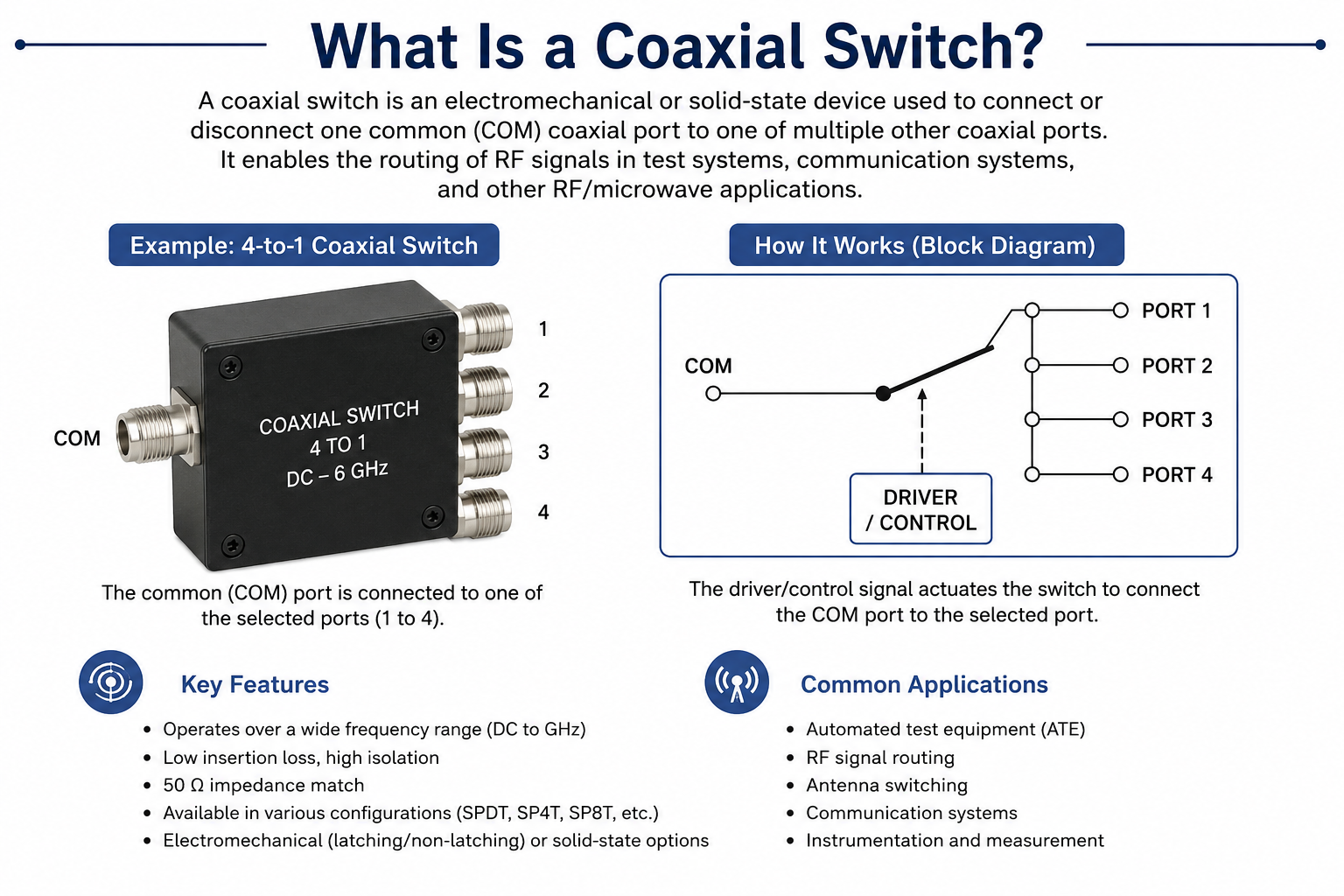
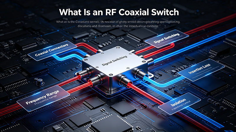
A coaxial switch is an RF component that controls the connection between coaxial transmission lines. Unlike standard electrical switches, coaxial switches are engineered to maintain precise impedance matching (typically 50 Ω or 75 Ω) and minimize signal degradation during switching operations. They use coaxial connectors (such as SMA, N-type, BNC, or TNC) to ensure proper signal transmission at frequencies from DC to over 40 GHz, and in high-frequency variants, up to 67 GHz.
Coaxial switches sit at the intersection of two worlds: the RF switching domain (which also includes solid-state RF switches and PIN-diode switches) and the microwave test domain (where signal paths must remain calibrated and repeatable). Whenever you need to redirect an RF or microwave signal between instruments, antennas, or DUTs (devices under test) without manually swapping cables, you are using a coaxial switch.
How Does a Coaxial Switch Work?
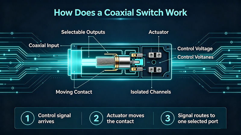
Most coaxial switches are electromechanical: they use a magnetic coil to physically move an internal RF contact from one position to another. The basic operating principle is:
- Actuation: When voltage is applied to the coil terminals, a magnetic field is generated.
- Contact movement: The magnetic force moves the RF contact from one position to another.
- Signal routing: The moving contact connects the common port to the selected throw port.
- Latching (optional): Some switches use latching mechanisms to maintain position without continuous power.
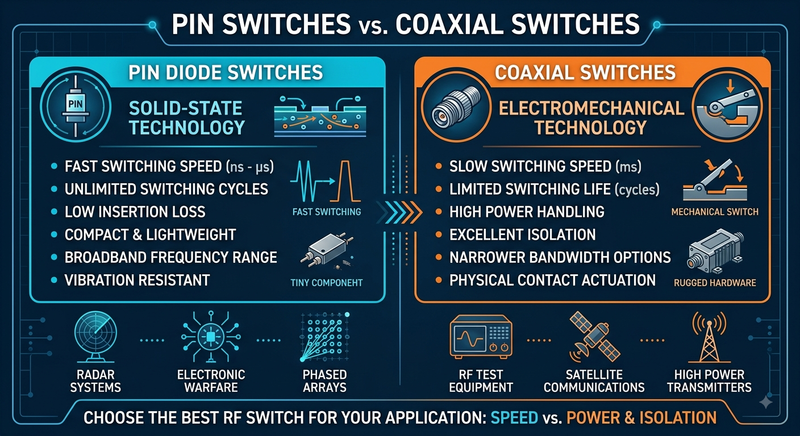
Solid-state coaxial switches work very differently. Instead of moving parts, they use semiconductor devices — typically PIN diodes or FETs — to create a low-loss path or a high-isolation block. Solid-state switches are much faster (nanoseconds vs. milliseconds), have effectively unlimited switching life, but trade off power handling and isolation. We compare both architectures in detail in the Electromechanical vs. Solid-State section below.
Main Types of Coaxial Switches
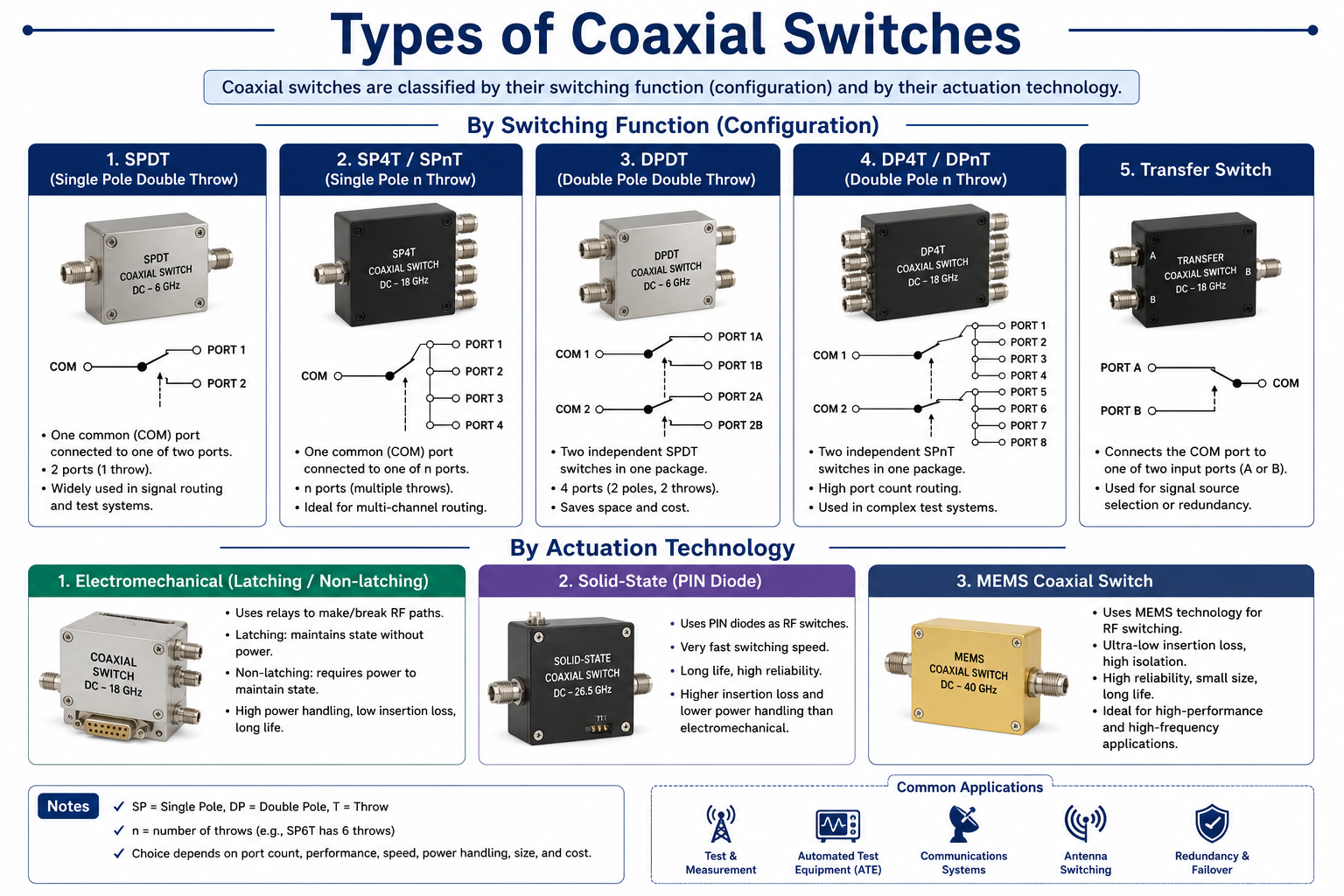
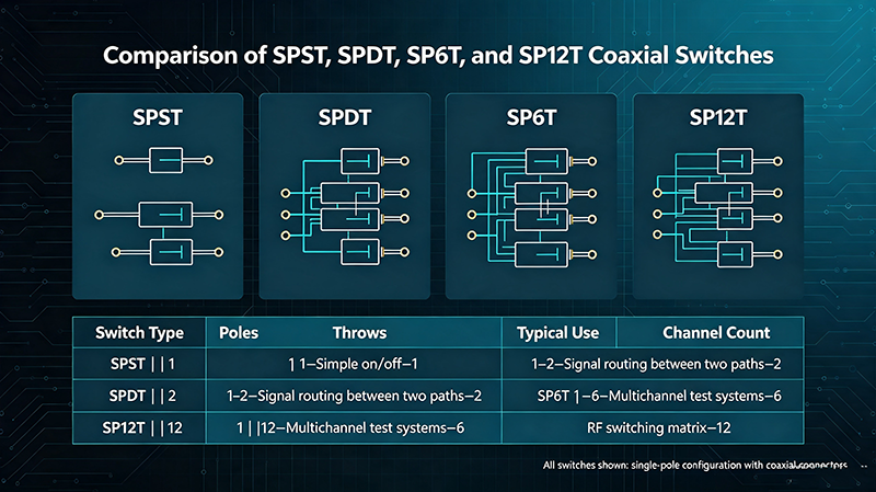
Coaxial switches are categorized by their pole/throw configuration. The most common types are listed below; each is then covered in detail.
| Type | Configuration | Typical Use |
|---|---|---|
| SPST | 1 × 1 | RF signal ON / OFF |
| SPDT | 1 × 2 | Signal routing between two paths |
| SP4T | 1 × 4 | Multi-channel selection |
| SP6T | 1 × 6 | RF test systems |
| SP12T | 1 × 12 | Automated test equipment |
| Transfer | 2 × 2 | Hot-swap / redundancy |
SPST Coaxial Switch
A SPST (Single-Pole Single-Throw) coaxial switch is the simplest form: a single RF path that is either connected or blocked. SPST switches are commonly used as RF on/off controls, transmit/receive blanking, and as building blocks inside larger subsystems. They offer low insertion loss when closed and high isolation when open.
SPDT Coaxial Switch
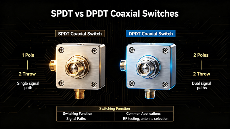
An SPDT (Single-Pole Double-Throw) coaxial switch provides one common RF port that can be connected to either of two output ports. It is the workhorse of RF signal routing, used in antenna switching, automated test equipment, redundancy switching, and bench-top measurement. SPDT RF switches are the highest-volume configuration and are available in latching and non-latching variants, DC up to 67 GHz.
SP4T Coaxial Switch
An SP4T coaxial switch routes a single common port to one of four outputs. It is widely used in multi-channel test systems, matrix switching building blocks, and any application that needs to connect one instrument to several antennas or DUTs. SP4T switches balance port count against RF performance — higher port counts increase insertion loss and reduce isolation.
SP6T Coaxial Switch
An SP6T coaxial switch extends the SP4T to six throws. SP6T models are popular in RF test systems that need to characterize multiple antennas or front-end modules without manual cable changes. They are commonly paired with vector network analyzers and used in production test racks.
SP12T Coaxial Switch
An SP12T coaxial switch provides 12 outputs from a single common. SP12T switches are the building blocks of automated test equipment (ATE) for cellular, Wi-Fi, Bluetooth, and GNSS modules. They dramatically reduce test time by replacing manual reconnects with a single switching event.
Transfer Coaxial Switch
A transfer (DPDT) coaxial switch connects two common ports to two alternate ports simultaneously — a make-before-break or break-before-make action. Transfer switches are used for redundancy and hot-swap in radar and communications, where a backup path must take over instantly when the primary path fails. See our guide on RF transfer switches for more.
Electromechanical vs. Solid-State RF Switches
Every RF switch falls into one of two broad technology families: electromechanical (moving parts inside a coaxial cavity) or solid-state (semiconductor junctions). Most coaxial switches are electromechanical because coaxial connectors cannot easily mate to a semiconductor package. Solid-state switches more often appear in microstrip or surface-mount form factors.
| Feature | Coaxial Switch | Solid-State RF Switch |
|---|---|---|
| Technology | Electromechanical | Semiconductor (PIN / FET) |
| Switching speed | 10–50 ms | < 1 µs (often ns) |
| Isolation | 60–90 dB | 30–60 dB (application dependent) |
| Power handling | Up to 1000 W peak | Usually lower |
| Switching life | 1–10 million cycles | Effectively unlimited |
| Insertion loss | 0.1–0.5 dB (broadband) | Frequency dependent, typically higher at low GHz |
| Typical application | Test systems, high-power routing | Fast RF switching, beam steering |
| Connector | SMA, N-type, 2.92 mm, 1.85 mm | SMT / microstrip |
Choose electromechanical coaxial switches for low insertion loss, high isolation, high power, and standardized coaxial connectors. Choose solid-state RF switches when you need nanosecond switching, unlimited cycling, or integration into a PCB.
Key Coaxial Switch Specifications
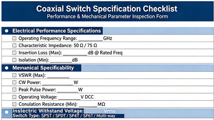
The numbers in a datasheet tell you whether the switch can perform in your system. The most useful ones to compare are:
| Specification | What It Means | Why It Matters |
|---|---|---|
| Frequency range | The operating bandwidth (e.g., DC–26.5 GHz) | Determines usable RF spectrum; must exceed your highest signal frequency. |
| Insertion loss | Signal loss through the switch when in the through path | Affects system efficiency and noise figure; lower is better. |
| Isolation | RF rejection between ports when disconnected | Prevents signal leakage that can damage stages or cause crosstalk. |
| VSWR | Voltage standing wave ratio at each port | Indicates impedance matching; closer to 1:1 is better. |
| Switching speed | Time required to change state (ms or µs) | Critical for automated testing and pulsed systems. |
| Switching life | Number of guaranteed switching operations | Determines long-term reliability and total cost of ownership. |
| Power handling | Maximum RF power (CW, peak, average) | Critical for high-power applications and radar pulses. |
| Impedance | Usually 50 Ω or 75 Ω | Must match the RF system to avoid reflections. |
| Connector type | SMA, N, 2.92 mm, 2.4 mm, 1.85 mm, BNC | Determines mechanical and RF compatibility with cables. |
Coaxial Switch vs. Other RF Switch Technologies
An RF switch is a broad category of devices used to route radio-frequency signals. A coaxial switch is a sub-category that uses coaxial transmission paths and connectors. Other members of the RF switch family include waveguide switches, solid-state switches, PIN-diode switches, and MEMS switches.
| Feature | Coaxial Switch | Waveguide Switch | Solid-State RF Switch |
|---|---|---|---|
| Frequency range | DC to 67 GHz | 18 GHz to 110 GHz+ | DC to ~40 GHz |
| Size | Compact | Large | Very small |
| Cost | Moderate | High | Low to moderate |
| Power handling | Up to 1000 W peak | Very high | Usually lower |
| Switching speed | 10–50 ms | 50–200 ms | < 1 µs |
| Typical application | General RF / microwave | Millimeter-wave, EHF | Fast switching, beam steering |
Coaxial switches dominate the DC–67 GHz range where coaxial connectors are the standard. Above ~67 GHz, waveguide switches take over because rectangular waveguide has lower loss than coaxial at mmWave and terahertz frequencies.
Coaxial Switch Applications
Coaxial switches are deployed wherever an RF or microwave signal must be routed between multiple paths. The most important application areas are:
RF Test and Measurement
Vector network analyzers, spectrum analyzers, and signal generators rely on coaxial switches to connect multiple DUTs and antennas without manual recabling. SP6T and SP12T switches are particularly common in production test racks.
Wireless Communications
Base stations and small cells use coaxial switches for antenna diversity, transmit/receive switching, and band selection. Latching SPDT switches are common in macro-cell tower-top units.
Radar Systems
Radar front ends use transfer switches to switch between the transmitter and the antenna, and SPDT switches to route between receiver channels. High-power coaxial switches handle the kilowatt-level pulses typical of surveillance and weather radar.
Aerospace and Defense
Avionics, electronic warfare, and satellite payloads use ruggedized coaxial switches qualified to MIL-STD-810 or equivalent. Hermetic sealing and extended temperature ranges are typical.
5G / 6G
5G FR2 (24–52 GHz) and emerging 6G bands push coaxial switches into the millimeter-wave domain. High-frequency coaxial switches with 2.4 mm or 1.85 mm connectors are used in 5G handset and base-station characterization.
Satellite Communications
Ground stations and LEO constellations use latching coaxial switches for redundancy on the antenna feed. Power consumption matters because many antennas are solar-powered.
Automated Test Equipment (ATE)
Cellular, Wi-Fi, Bluetooth, and GNSS modules are production-tested with multi-throw coaxial switches (SP6T, SP12T) to minimize test time and maximize throughput.
How to Select a Coaxial Switch
Selecting the right coaxial switch comes down to nine parameters. Walk through them in this order:
- Frequency range. Pick a switch that covers your full operating band, not just the center. Common ranges: DC–6 GHz, DC–18 GHz, DC–26.5 GHz, DC–40 GHz, DC–50 GHz, DC–67 GHz.
- RF power. Specify both average power (CW), peak power (pulsed), and any duty-cycle limits. For radar pulses, verify peak power is well within the switch’s rating.
- Insertion loss. For sensitive chains, budget < 0.3 dB through the switch. For less critical paths, 0.5–1.0 dB is acceptable.
- Isolation. 60–90 dB is typical. Receiver chains behind the switch typically need > 60 dB to prevent crosstalk.
- VSWR. 1.10:1 to 1.30:1 across the operating band is typical. Tighter VSWR is better but more expensive.
- Switching speed. 10–50 ms is typical for electromechanical. For ATE or pulsed applications, faster is better — or move to a solid-state switch.
- Switching life. 1–10 million cycles. Calculate expected cycles over the system lifetime and choose with margin.
- Connector type. SMA for DC–18 GHz, 2.92 mm for DC–40 GHz, 2.4 mm for DC–50 GHz, 1.85 mm for DC–67 GHz, N-type for lower-frequency high-power applications.
- Control interface. TTL, USB, Ethernet, RS-232, or parallel control. Pick what your test software already supports.
High-Frequency Coaxial Switches (Up to 67 GHz)
As coaxial RF switches push into the millimeter-wave domain, every parameter — insertion loss, isolation, connector precision, calibration — becomes harder. dbdesign’s high-frequency coaxial switches up to 67 GHz address the most demanding applications:
- 67 GHz frequency coverage for 5G FR2, 6G research, and E-band backhaul.
- Low insertion loss maintained across the full band — critical for receiver noise figure.
- High port-to-port isolation to prevent leakage between test channels.
- Tight VSWR for matched measurements at mmWave.
- 1.85 mm connector technology rated to 67 GHz with precision-machined interfaces.
- High-frequency test systems — VNA, spectrum analyzer, and signal source automation.
- Semiconductor testing — on-wafer and packaged device characterization.
- 5G/6G handset and base-station testing across FR1 and FR2.
- Aerospace & defense mmWave systems for radar, EW, and SATCOM payloads.
Coaxial Switch Frequency Ranges
Coaxial switches are typically sold by frequency range, and the connector and price scale with it:
| Frequency Range | Typical Connector | Typical Application |
|---|---|---|
| DC – 6 GHz | SMA, BNC, N-type | Wireless, telemetry, broadcast |
| DC – 18 GHz | SMA | Wi-Fi, LTE, microwave radios |
| DC – 26.5 GHz | SMA, 3.5 mm | 5G FR1, radar, satcom |
| DC – 40 GHz | 2.92 mm | 5G FR2, mmWave research |
| DC – 50 GHz | 2.4 mm | mmWave, 5G / 6G |
| DC – 67 GHz | 1.85 mm | 67 GHz RF testing, 6G research |
Common Coaxial Switch Configurations
Engineers often describe a coaxial switch by its configuration string, such as “SPDT, latching, 28 VDC, SMA.” The configuration block tells you:
- Pole/throw: SPST, SPDT, SP3T, SP4T, SP6T, SP12T, transfer.
- Actuation: latching (maintains position without power) or non-latching (returns to default when power removed).
- Coil voltage: typically 5 V, 12 V, 15 V, 24 V, or 28 V.
- Indicator contacts: optional mechanical or electronic contact that reports the switch’s true position.
- Connector and orientation: SMA, N-type, 2.92 mm, 2.4 mm, 1.85 mm — and the body style (panel, in-line, right-angle).
Coaxial Switch FAQs
Conclusion
The coaxial switch is one of the most important building blocks in any RF or microwave system. Whether you are routing signals in a test rack, switching antennas on a tower, building a redundancy path in radar, or characterizing devices at 67 GHz, the right coaxial switch comes down to matching frequency range, insertion loss, isolation, VSWR, and connector type to your application. Use the selection checklist above, walk the nine parameters in order, and let the application — not the spec sheet — drive your choice.
Need Help Selecting a Coaxial Switch?
Our technical team can help you find the right coaxial switch for your application — from DC to 67 GHz.
Contact Technical Support