




























Top 5 Factors Causing Insertion Loss in RF Switches and How to Minimize Them
Insertion loss is one of the most critical performance parameters when selecting an RF switch for microwave and high-frequency applications. Excessive insertion loss can reduce signal strength, degrade system sensitivity, increase power consumption, and negatively impact communication reliability.
For applications such as satellite communication, radar systems, 5G networks, automatic test equipment (ATE), and wireless infrastructure, minimizing RF switch insertion loss is essential for maintaining signal integrity.
This article explains the top 5 factors causing insertion loss in RF switches and provides practical methods to reduce signal degradation.
What Is Insertion Loss in an RF Switch?
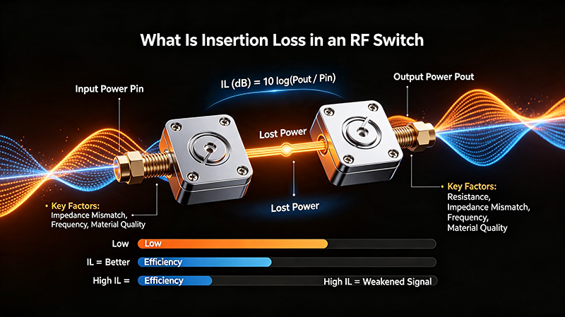
Insertion loss refers to the amount of signal power lost when an RF switch is inserted into a transmission path. It is usually measured in decibels (dB) and represents the difference between the input power and output power.
Insertion Loss (dB) = -10 × log10(Output Power / Input Power)
A lower insertion loss value indicates better RF switch performance. For example, a switch with 0.5 dB insertion loss will introduce significantly less signal attenuation than a switch with 2 dB loss.
Why Is Low Insertion Loss Important in RF Systems?
RF signals operate at extremely high frequencies where even small losses can affect overall system performance. High insertion loss can result in:
- Reduced transmitter output power efficiency
- Lower receiver sensitivity
- Reduced communication range
- Increased system noise figure
- Poor signal-to-noise ratio (SNR)
Therefore, engineers must carefully evaluate RF switch specifications before integrating them into high-performance microwave systems.
Top 5 Factors Causing Insertion Loss in RF Switches
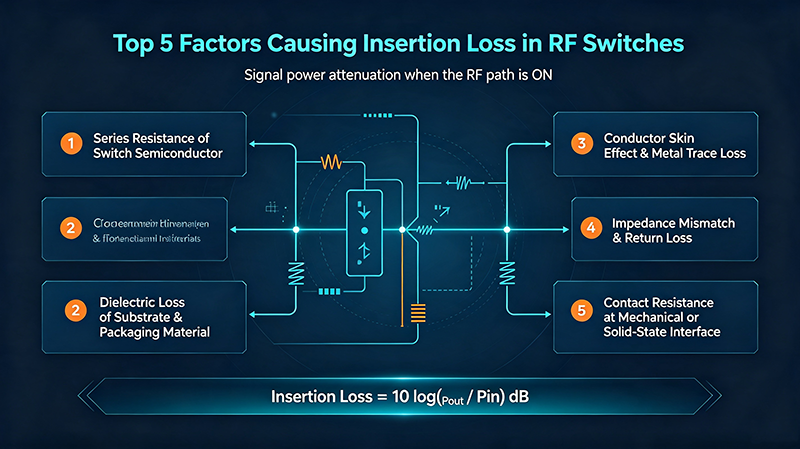
1. Internal Switch Resistance
The internal resistance of an RF switch is one of the primary contributors to insertion loss. In electromechanical RF switches, contact resistance between switching elements can introduce additional signal attenuation.
For solid-state switches such as PIN diode switches, the forward resistance of the diode also affects conduction loss.
How to Minimize It:
- Select RF switches with low contact resistance.
- Use high-quality switching components and materials.
- Choose PIN diode switches optimized for low series resistance.
- Verify insertion loss specifications at the actual operating frequency.
2. Poor RF Connector and Transmission Line Design
Connectors, transmission lines, and internal RF structures can significantly impact insertion loss. Improper impedance matching or low-quality connectors may create additional attenuation.
Common causes include:
- Incorrect connector selection
- Poor PCB layout design
- Impedance discontinuities
- High-frequency signal reflections
How to Minimize It:
- Use precision RF connectors such as SMA, 2.92mm, or 1.85mm connectors.
- Maintain a consistent 50-ohm impedance path.
- Optimize PCB microwave transmission line design.
- Perform RF simulation before production.
3. Frequency Range Limitations
Insertion loss increases as operating frequency rises. A switch designed for low-frequency applications may experience significant signal degradation when used at microwave or millimeter-wave frequencies.
| Frequency Range | Typical Application | Insertion Loss Challenge |
|---|---|---|
| DC - 6 GHz | Wireless communication | Low loss achievable |
| 6 - 18 GHz | Radar and test systems | Higher conductor loss |
| 18 - 67 GHz | Millimeter-wave applications | Strict design requirements |
How to Minimize It:
- Select switches rated for the required frequency range.
- Avoid operating near the maximum frequency limit.
- Choose microwave switches specifically designed for high-frequency applications.
4. Impedance Mismatch and VSWR
Impedance mismatch causes signal reflections, which increase insertion loss. RF switches must maintain excellent VSWR performance to ensure efficient power transfer.
Poor impedance matching can create:
- Signal reflections
- Standing waves
- Additional power loss
- Reduced system efficiency
How to Minimize It:
- Select RF switches with low VSWR ratings.
- Maintain 50-ohm impedance throughout the RF path.
- Use proper calibration during system testing.
- Verify S-parameter performance using a vector network analyzer (VNA).
5. Manufacturing Quality and Material Selection
The quality of materials and manufacturing processes directly affects RF switch performance. Poor mechanical tolerances, unsuitable dielectric materials, and inconsistent assembly can increase insertion loss.
How to Minimize It:
- Select RF switch manufacturers with strict quality control.
- Use low-loss dielectric materials.
- Ensure accurate machining of RF components.
- Perform full RF testing before shipment.
How to Reduce RF Switch Insertion Loss: Best Practices

1. Choose the Right RF Switch Technology
Different RF switch technologies have different insertion loss characteristics.
- Electromechanical RF Switches: Excellent isolation and low insertion loss.
- PIN Diode Switches: Fast switching speed and compact design.
- MEMS RF Switches: Low power consumption and excellent RF performance.
2. Optimize the RF Signal Path
A carefully designed RF path can significantly reduce losses.
- Minimize unnecessary connectors.
- Reduce cable length.
- Avoid sharp transmission line bends.
- Use high-quality RF cables.
3. Perform Accurate RF Testing
Testing with professional equipment is essential for identifying insertion loss problems.
Common RF measurement tools include:
- Vector Network Analyzer (VNA)
- Spectrum Analyzer
- RF Power Meter
RF Switch Selection Guide for Low Insertion Loss
| Parameter | Recommended Requirement |
|---|---|
| Insertion Loss | As low as possible, typically below 1 dB |
| Frequency Range | Match system operating frequency |
| VSWR | Preferably below 1.5:1 |
| Isolation | High isolation for sensitive applications |
| Power Handling | Suitable for input RF power level |
Conclusion
Insertion loss is a key factor affecting RF switch performance, especially in high-frequency microwave systems. The main causes include internal resistance, poor RF design, frequency limitations, impedance mismatch, and manufacturing quality issues.
By selecting the correct RF switch technology, optimizing the signal path, maintaining proper impedance control, and choosing a reliable manufacturer, engineers can significantly reduce insertion loss and improve overall system performance.
For demanding applications such as radar, satellite communication, 5G infrastructure, and automated RF testing, selecting a high-performance RF microwave switch with low insertion loss is essential for achieving reliable signal transmission.
About the Author — MeiXun Team
Chief Engineer Wang
High-tech Enterprise, Feifeng Talent
Chief Engineer Wang graduated with a master's degree in high-power microwave from the Institute of Electronics, University of Chinese Academy of Sciences.
View Full Profile- RF Switch Circuit Diagram
- RF Switch
- Ohm's Law
- dBm to Watt
- mW to dBm
- Wavelength to Frequency
- RF Connector
- SMA Connector
- RF Switch Module
- RF Coupler
- RF PIN Switch
- Microwave Coaxial Switch
- PIN Switch
- Coaxial RF Switch
- Waveguide Switch
- Microwave Switch
- Low Noise Amplifier
- PIN Diode Switch
- Coaxial Switch
- RF Microwave Switch
- SPST Switch