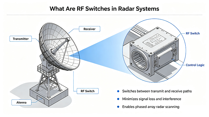
High power RF switches are essential components in modern RF and microwave systems where signal routing must be performed while handling substantial radio-frequency power. They are widely used in radar, wireless communications, satellite systems, RF testing, electronic warfare, and high-power microwave equipment.
Unlike conventional RF switches designed primarily for low- or medium-power signals, high power RF switches must manage additional challenges such as heat generation, voltage stress, arcing, contact reliability, insertion loss, isolation, and power handling capability.
What Are High Power RF Switches?
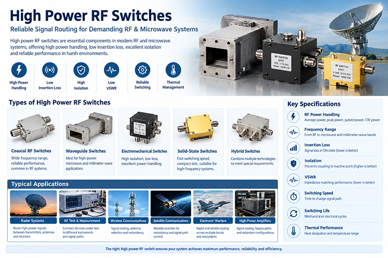
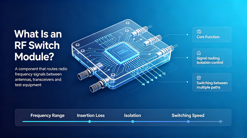
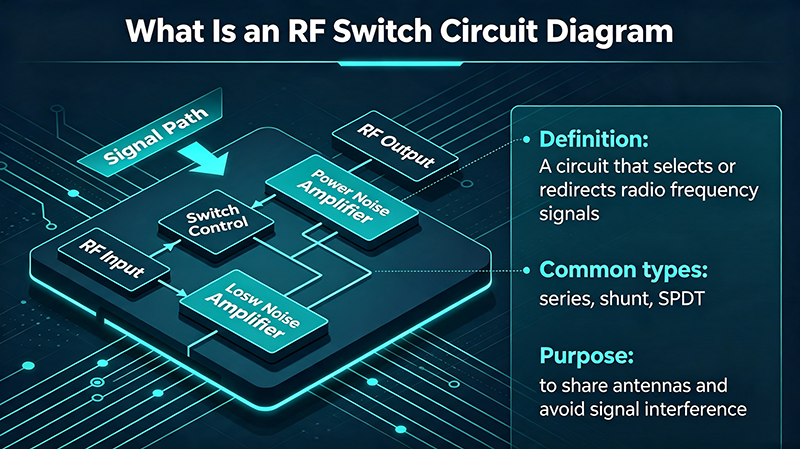
A high power RF switch is an RF or microwave switching device designed to selectively connect a signal source to one or more transmission paths while maintaining reliable operation at elevated RF power levels.
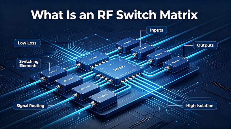
The switch can route signals between antennas, transmitters, receivers, test equipment, filters, amplifiers, attenuators, and other microwave components. Depending on the configuration, a high power RF switch can provide single-pole switching, multiple output paths, or more complex signal-routing functions.
Typical high power RF switch designs are available in coaxial, waveguide, electromechanical, solid-state, and hybrid configurations. The appropriate technology depends on frequency, power level, switching speed, isolation requirements, lifetime, and system architecture.
Why High Power RF Switching Is Important
High-power transmit systems cannot always use standard RF switches because the switching device may experience excessive electrical and thermal stress. A switch that performs well at low power may suffer from increased insertion loss, contact damage, dielectric breakdown, or arcing when subjected to higher RF power.
High power RF switches are therefore engineered to provide:
-
High RF power handling capability
-
Low insertion loss
-
High isolation between ports
-
Reliable switching under demanding operating conditions
-
Low VSWR across the specified frequency range
-
High mechanical or electrical switching reliability
-
Effective thermal management
Types of High Power RF Switches
1. High Power Coaxial RF Switches
Coaxial RF switches are commonly used when RF signals are transmitted through coaxial cables and connectors. They can cover a broad range of frequencies and are available in several port configurations.
High power coaxial switches are frequently implemented using electromechanical mechanisms because physical contacts can provide high isolation and relatively low RF loss over a wide frequency range.
2. High Power Waveguide Switches
Waveguide switches are designed for microwave and millimeter-wave applications where waveguide transmission lines are preferred. Their structures are particularly suitable for high-power microwave systems because waveguides can handle significant RF power while maintaining low transmission loss.
Applications include radar systems, satellite communications, microwave test systems, RF power distribution networks, and high-power transmitters.
3. Electromechanical RF Switches
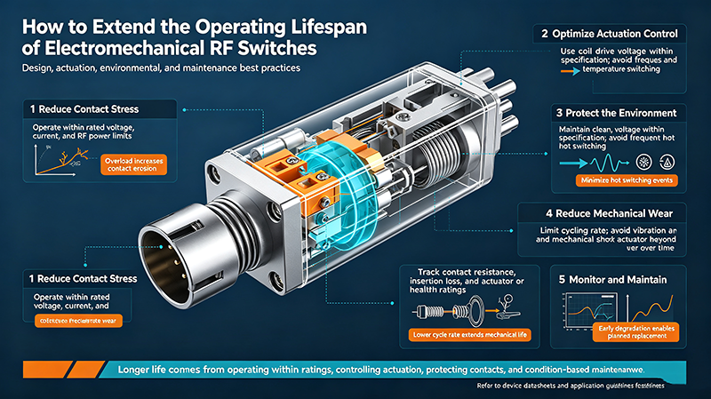
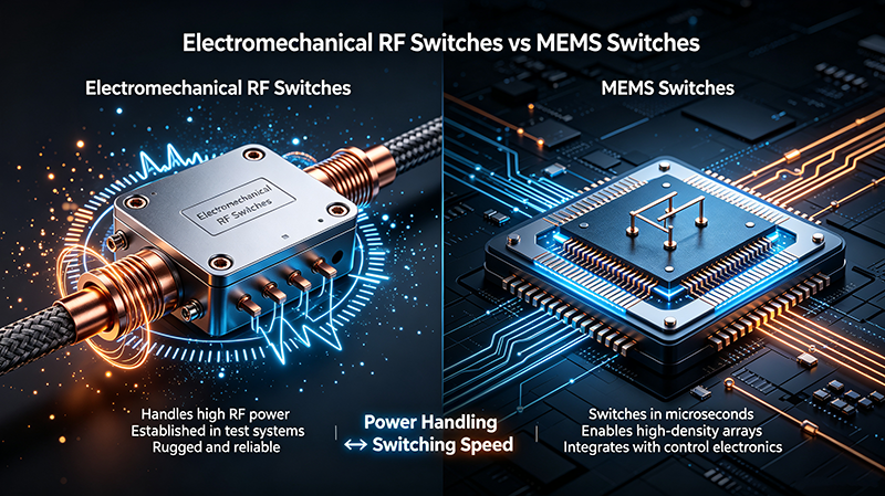
Electromechanical RF switches use mechanical movement to establish or interrupt an RF signal path. They are widely used in applications where high isolation, low insertion loss, and high power handling are more important than extremely fast switching.
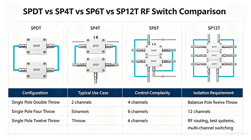
Typical configurations include SPDT, SPST, DPDT, transfer switches, and multi-throw RF switching systems.
4. Solid-State High Power RF Switches
Solid-state RF switches use semiconductor devices rather than moving mechanical contacts. Technologies can include PIN diodes, FET-based switches, and other semiconductor structures.
The major advantage is very fast switching speed. However, power handling, linearity, thermal performance, and insertion loss must be carefully evaluated for high-power applications.
5. Hybrid RF Switches
Hybrid RF switches combine characteristics of different switching technologies to meet specialized requirements. They can be used when an application requires a balance between switching speed, RF power handling, isolation, reliability, and insertion loss.
Common High Power RF Switch Configurations
|
Configuration
|
Description
|
Typical Application
|
|
SPST
|
Single-pole, single-throw switching
|
RF signal on/off control
|
|
SPDT
|
One input switched between two outputs
|
Transmitter/receiver routing
|
|
SPnT
|
One input switched among multiple outputs
|
RF test and measurement systems
|
|
DPDT
|
Two-pole, double-throw switching
|
More complex RF signal routing
|
|
Transfer Switch
|
Routes multiple signal paths simultaneously
|
Redundant RF systems and test equipment
|
Key Specifications of High Power RF Switches
Choosing a high power RF switch requires more than checking its maximum power rating. Several RF and mechanical specifications affect real-world performance.
RF Power Handling
Power handling is one of the most important parameters. It indicates how much RF power the switch can safely handle under specified conditions.
Power may be specified as average power, peak power, pulsed power, or CW power. A switch designed for pulsed radar operation may have a very different power specification from one intended for continuous-wave transmission.
Important: Always evaluate RF power specifications together with frequency, duty cycle, ambient temperature, load VSWR, switching state, and pulse characteristics. A maximum power value without these conditions may not fully describe actual system capability.
Frequency Range
The switch must cover the complete operating frequency range of the RF system. High power RF switches are available for applications ranging from lower RF frequencies to microwave and millimeter-wave bands.
As frequency increases, parasitic capacitance, inductance, connector geometry, transmission-line dimensions, and mechanical tolerances become increasingly important.
Insertion Loss
Insertion loss represents the signal power lost when the switch is in the ON state. Lower insertion loss is generally desirable because it reduces attenuation in the RF signal path.
Insertion Loss (dB) = 10 × log10(Pin / Pout)
For high-power transmitters, even a small amount of insertion loss can generate substantial heat. For this reason, low-loss switch designs can be particularly important in high-power applications.
Isolation
Isolation indicates how effectively the switch prevents RF energy from coupling into an inactive port. High isolation is important when protecting receivers or preventing unwanted interaction between multiple transmit paths.
High isolation is especially valuable in radar, test systems, communication infrastructure, and multi-channel RF architectures.
VSWR
Voltage standing wave ratio, or VSWR, describes the impedance matching performance of an RF transmission path. Poor matching can increase reflected power and create additional stress in high-power systems.
When selecting a high power RF switch, examine VSWR across the entire operating frequency range rather than relying on a single nominal value.
Switching Speed
Switching speed determines how quickly the device can change from one RF path to another. Solid-state switches can provide extremely fast switching, while electromechanical switches generally operate more slowly.
The required switching speed depends on the application. Automated RF test systems may prioritize switching time, whereas a radar subsystem may place greater emphasis on isolation, power handling, and reliability.
Switching Life
Electromechanical RF switches have a finite mechanical operating life. Manufacturers may specify switching cycles under particular electrical and mechanical conditions.
For systems that perform frequent switching, expected cycle count should be evaluated alongside RF power, load conditions, switching frequency, and environmental requirements.
High Power RF Switches for Pulsed Applications
Radar and other pulsed RF systems create unique requirements for RF switching. Peak power can be substantially higher than average power, while pulse width, pulse repetition frequency, duty cycle, and waveform characteristics influence thermal and electrical stress.
For pulsed applications, engineers should consider:
-
Peak RF power
-
Average RF power
-
Pulse width
-
Pulse repetition frequency
-
Duty cycle
-
Maximum load VSWR
-
Switching timing
-
Arc and breakdown margins
A switch rated for a particular peak power should not automatically be assumed to support the same power under continuous-wave operation.
High Power RF Switches vs. Standard RF Switches
|
Parameter
|
Standard RF Switch
|
High Power RF Switch
|
|
Power Handling
|
Low to moderate
|
Designed for higher RF power levels
|
|
Thermal Requirements
|
Often less demanding
|
More important due to RF losses
|
|
Isolation
|
Application dependent
|
Often critical for transmit/receive systems
|
|
Mechanical Design
|
Depends on technology
|
May require reinforced contacts and RF structures
|
|
Applications
|
Instrumentation, communications, general RF
|
Radar, high-power transmitters, RF test systems
|
Applications of High Power RF Switches
Radar Systems
Radar systems use RF switches to route high-power signals between transmitters, antennas, receivers, filters, and other RF subsystems. Waveguide and coaxial high-power switches can be selected according to frequency and power requirements.
RF and Microwave Test Equipment
Automated test systems frequently use RF switches to connect a device under test to different instruments, signal paths, filters, or measurement channels. High power switching capability is useful when testing transmitters, amplifiers, antennas, and other power-handling devices.
Wireless Communications
Communication infrastructure may use RF switching for signal routing, antenna selection, redundancy, and system configuration. The required switch characteristics depend on frequency band, transmitted power, isolation, and switching architecture.
Satellite Communications
Satellite and ground-station RF systems can use high-reliability switches for redundancy and signal-path control. Weight, size, reliability, power handling, and environmental requirements can all influence the switch design.
Electronic Warfare Systems
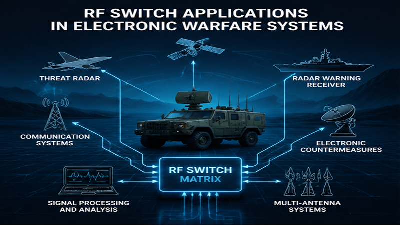
Electronic warfare equipment can require rapid and reliable routing of RF signals across multiple frequency bands and subsystems. Depending on the architecture, both solid-state and electromechanical technologies may be considered.
High-Power RF Amplifiers
RF switches can be integrated with high-power amplifiers to route signals, provide bypass paths, support maintenance configurations, or connect redundant amplifier modules.
How to Select a High Power RF Switch
A systematic selection process helps ensure that the switch can operate safely under actual RF conditions.
-
Define the frequency range. Identify the minimum and maximum operating frequencies.
-
Determine RF power. Specify both continuous and peak power where applicable.
-
Identify the switching topology. Select SPST, SPDT, SPnT, DPDT, transfer, or another configuration.
-
Check insertion loss. Determine the maximum acceptable attenuation.
-
Check isolation. Evaluate isolation requirements between active and inactive ports.
-
Evaluate VSWR. Confirm impedance matching across the operating band.
-
Determine switching speed. Match the switch response time to the system timing requirements.
-
Evaluate switching life. For electromechanical switches, estimate the required operating cycles.
-
Consider connectors and transmission media. Coaxial and waveguide interfaces have different frequency and power characteristics.
-
Evaluate environmental requirements. Consider temperature, humidity, vibration, altitude, and other operating conditions.
Thermal Considerations in High Power RF Switching
Even a low insertion-loss RF switch dissipates some RF energy. At high transmitted power, this loss can become a significant heat source.
For example, if a switch has an insertion loss of 0.5 dB, its output power is lower than its input power. The corresponding dissipated power can become substantial when the input power reaches hundreds or thousands of watts.
Thermal design may involve conductive heat paths, appropriate mounting structures, heat sinks, forced-air cooling, or other system-level methods depending on the switch architecture.
High Power RF Switches and Load Mismatch
Load mismatch is another important consideration in high-power RF systems. A high VSWR load can cause reflected RF energy to return toward the switch and transmitter.
Therefore, switch power ratings should be interpreted together with the specified load VSWR. In demanding applications, engineers may need to verify performance under worst-case mismatch rather than under an ideal 50-ohm load.
Electromechanical vs. Solid-State High Power RF Switches
|
Feature
|
Electromechanical
|
Solid-State
|
|
Switching Speed
|
Typically slower
|
Typically very fast
|
|
Mechanical Wear
|
Present
|
No mechanical contacts
|
|
Isolation
|
Can be very high
|
Technology dependent
|
|
Insertion Loss
|
Often low
|
Frequency and semiconductor dependent
|
|
Power Handling
|
Can be high
|
Highly dependent on device technology and thermal design
|
|
Lifetime
|
Limited by mechanical operation
|
No mechanical switching wear
|
Common Design Challenges
High power RF switch design involves several engineering challenges that are less significant in low-power switching applications.
-
RF arcing: High electric-field concentrations can create breakdown risks.
-
Thermal stress: RF losses can generate heat and affect reliability.
-
Contact degradation: Mechanical contacts may deteriorate under repeated high-power switching.
-
Impedance discontinuities: Poor RF geometry can increase reflections and VSWR.
-
Parasitic effects: Capacitance and inductance become increasingly important at microwave frequencies.
-
Power compression: Semiconductor switches may exhibit nonlinear behavior when approaching their power limits.
Frequently Asked Questions About High Power RF Switches
What is a high power RF switch?
A high power RF switch is a device designed to route radio-frequency or microwave signals while handling substantially higher RF power than typical low-power switching components. Its specifications include power handling, frequency range, insertion loss, isolation, VSWR, and switching characteristics.
What is the difference between a high power RF switch and a microwave switch?
A microwave switch is generally defined by its operating frequency range, while a high power RF switch is characterized by its ability to handle elevated RF power. A single device can be both a microwave switch and a high power RF switch.
Are waveguide switches suitable for high-power applications?
Waveguide switches are commonly used in high-power microwave systems because waveguide transmission structures can support substantial RF power. The actual power capability depends on frequency, waveguide size, switch construction, environmental conditions, and the manufacturer's specifications.
Which is faster, an electromechanical or solid-state RF switch?
Solid-state RF switches generally provide much faster switching than electromechanical switches. However, the appropriate technology depends on the complete application because power handling, isolation, insertion loss, linearity, and reliability also need to be considered.
What specifications should I provide when ordering a high power RF switch?
Important information includes frequency range, RF power, peak and average power, switching configuration, connector or waveguide interface, insertion loss, isolation, VSWR, switching speed, switching life, control voltage, environmental conditions, and mechanical dimensions.
Conclusion
High power RF switches are critical components for routing RF and microwave signals in demanding applications such as radar, satellite communications, wireless infrastructure, RF test systems, and high-power transmitters.
The correct switch should be selected based on the complete operating environment rather than power rating alone. Frequency range, peak and average power, insertion loss, isolation, VSWR, switching speed, switching life, thermal performance, and interface configuration should all be evaluated together.
For demanding RF systems, understanding these parameters allows engineers to select a switching solution that matches the electrical, mechanical, and environmental requirements of the application.
Related Keywords: high power RF switches, high power RF switch, high power microwave switch, high power coaxial RF switch, high power waveguide switch, RF power switch, microwave RF switch, high power microwave switches, RF switch power handling, high power SPDT RF switch, high power SPST RF switch, RF switch for radar, RF switch for high power amplifier, high power RF switching, high power RF components, RF switch isolation, RF switch insertion loss, RF switch VSWR, high frequency RF switch, electromechanical RF switch.