




























Coaxial RF switches are the workhorses of RF signal routing in countless applications, from cellular base stations to laboratory test equipment. With their standardized coaxial connectors, robust electromechanical designs, and proven reliability, these switches provide versatile signal routing solutions across the entire RF spectrum. This guide explains coaxial RF switch technology, types, specifications, and applications.
What is a Coaxial RF Switch?
Definition
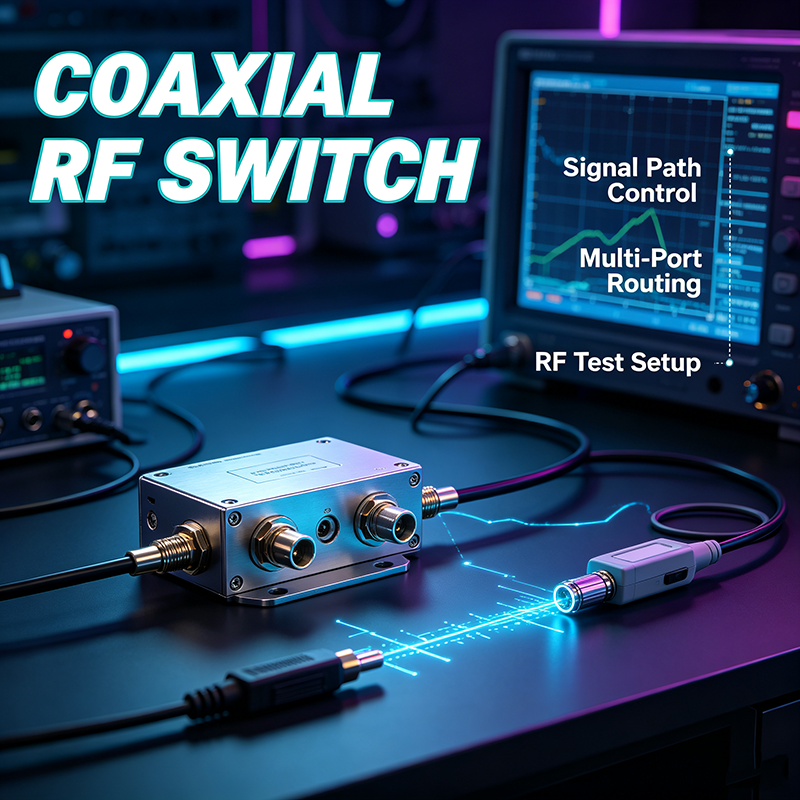
A coaxial RF switch is an electromechanical component that routes high-frequency signals between different paths using coaxial transmission line structures. These switches maintain 50-ohm (or 75-ohm) impedance throughout the signal path, providing excellent RF performance with standardized connector interfaces for easy system integration.
Coaxial RF switches use electromechanical actuators to physically move RF contacts within a coaxial structure that maintains consistent impedance throughout the switching mechanism. The coaxial design provides a controlled impedance environment for signals while the standardized connectors enable quick connection to test equipment, antennas, and other RF components.
These switches are distinguished from other RF switch types by their use of coaxial connectors (SMA, N-Type, BNC, etc.) and their electromechanical operation. While not as fast as solid-state switches, coaxial RF switches offer excellent RF performance, high power handling, and proven reliability for professional and industrial applications.
Key Features of Coaxial RF Switches
- Standardized Connectors: SMA, N-Type, BNC, and other common RF interfaces
- Excellent Isolation: 60-90 dB typical for electromechanical designs
- High Power Handling: Up to 500W CW for high-power models
- Broad Frequency Range: DC to 67 GHz with appropriate connectors
- Reliable Performance: Proven electromechanical technology
- Easy Integration: Standard connectors simplify system design
Types of Coaxial RF Switches
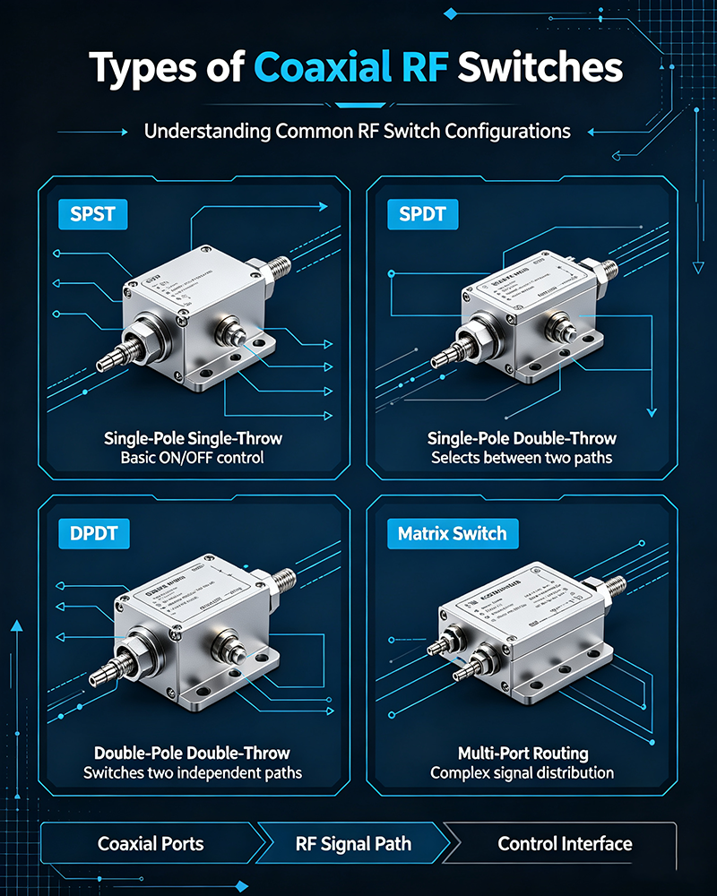
Coaxial RF switches come in several configurations to meet different signal routing requirements.
SPDT Coaxial Switches
Single-Pole Double-Throw switches route one input to one of two outputs. The most common configuration for T/R switching, source selection, and redundancy applications.
DPDT Coaxial Switches
Double-Pole Double-Throw switches simultaneously route two signals. Used in differential systems and transfer switching applications.
Transfer Switches
Special switches that swap connections between two pairs of ports. Essential for redundant communication systems and primary/backup configurations.
Multi-Throw Switches
SP3T through SP8T switches route signals to multiple outputs. Used in multi-antenna systems and test configurations.
Matrix Switches
Multiple inputs to multiple outputs routing. Used in complex test systems and large-scale signal routing applications.
Bypass Switches
Route signals around components for maintenance or test purposes. Common in redundancy systems and network protection.
Switch Mechanism Types
Latching Switches
Maintain position even when power is removed using magnetic latching mechanism. Ideal for power-sensitive applications and fail-safe operation. Common in redundancy systems.
Non-Latching (Failsafe) Switches
Return to default position when power is removed. Suitable for safety applications where default state is preferred. Simpler design and lower cost.
Motorized Switches
Include integrated motor drives for automated switching. Used in test systems and remote applications requiring computer control.
Common Connector Types
Coaxial RF switches are available with various connector types, each suited for different frequency ranges and applications.
| Connector Type | Frequency Range | Impedance | Typical Applications |
|---|---|---|---|
| BNC | DC - 4 GHz | 50Ω | Test equipment, video, legacy systems |
| TNC | DC - 11 GHz | 50Ω | Industrial, vibration-prone environments |
| SMA | DC - 27 GHz | 50Ω | Microwave, test equipment, communications |
| N-Type | DC - 18 GHz | 50Ω | High power, base stations, broadcast |
| 7/16 DIN | DC - 7.5 GHz | 50Ω | Very high power, cellular base stations |
| 2.92mm (K) | DC - 40 GHz | 50Ω | Precision test, millimeter-wave |
| 2.4mm | DC - 50 GHz | 50Ω | Precision millimeter-wave applications |
| 1.85mm (V) | DC - 67 GHz | 50Ω | Highest frequency precision applications |
| F-Type | DC - 3 GHz | 75Ω | CATV, video distribution |
Key Coaxial RF Switch Specifications
Understanding coaxial RF switch specifications ensures proper component selection and optimal system performance.
Primary Specifications
1. Frequency Range
The operating frequency band determined by the connector type and switch design. Most coaxial switches operate from DC to 26.5 GHz, with precision models extending to 67 GHz.
2. Insertion Loss
Signal power lost in the ON state. Coaxial switches typically achieve 0.2-0.5 dB insertion loss, providing excellent signal transmission in most applications.
3. Isolation
Signal blocking between ports in the OFF state. Coaxial switches provide 60-90 dB isolation, protecting sensitive receivers and preventing signal interference.
4. VSWR
Impedance matching quality. Lower VSWR (closer to 1:1) means better matching and less signal reflection. Typically 1.2:1 to 1.5:1 for quality switches.
5. Power Handling
Maximum RF power the switch can handle. Varies from watts for small SMA switches to hundreds of watts for N-Type and 7/16 DIN switches.
6. Switching Speed
Time to change states. Coaxial switches typically switch in 3-15 milliseconds, suitable for most applications but slower than solid-state alternatives.
| Parameter | Typical Range | Notes |
|---|---|---|
| Frequency Range | DC - 67 GHz | Depends on connector |
| Insertion Loss | 0.2 - 0.5 dB | Excellent for coax switches |
| Isolation | 60 - 90 dB | High for mechanical designs |
| VSWR | 1.1:1 - 1.5:1 | Low reflection |
| CW Power (SMA) | 10 - 50 W | Smaller connectors |
| CW Power (N-Type) | 100 - 500 W | Larger connectors |
| Switching Speed | 3 - 15 ms | Typical range |
| Lifetime | 10^6 - 10^7 cycles | Mechanical design |
Secondary Specifications
- Control Voltage: 12V, 24V, or 28V DC typical
- Position Indicators: TTL or form C contacts for status
- Operating Temperature: Standard or extended ranges
- Actuator Type: Latching, failsafe, or momentary
- Indicator Type: LED, electrical, or mechanical
- MTBF: Reliability specifications for mission-critical applications
Common Applications
Test and Measurement
Lab instruments and production test systems use coaxial switches for routing signals between devices under test and measurement equipment. Essential for automated test systems.
Cellular Base Stations
Base station equipment uses coaxial switches for T/R switching, antenna diversity, and redundancy in cellular networks from 2G through 5G.
Satellite Communications
Ground stations and satellite communication systems use coaxial switches for redundancy, polarization switching, and signal routing.
Broadcast Systems
TV and radio broadcast systems use high-power coaxial switches for switching between main and backup transmitters with minimal signal interruption.
Military Communications
Defense systems use rugged coaxial switches for reliable signal routing in harsh environments with MIL-SPEC requirements.
Radar Systems
Weather and military radar systems use coaxial switches for receiver protection, antenna switching, and calibration signal routing.
Medical Equipment
MRI systems and medical imaging equipment use coaxial switches for signal routing in diagnostic applications requiring high reliability.
Industrial Automation
Manufacturing test systems and process control use coaxial switches for automated RF testing and quality assurance.
Why Test Systems Prefer Coaxial Switches
Test and measurement applications particularly benefit from coaxial RF switches due to their standardized connectors that match common test equipment, excellent isolation for accurate measurements, and proven reliability for repeated test cycles.
Advantages and Limitations
Key Advantages
- Excellent isolation (60-90 dB)
- Standard coaxial connectors
- High power handling capability
- Low insertion loss
- Broad frequency coverage
- Proven reliability
- Easy system integration
- Wide variety of configurations
- Position indicators available
- Long operational life
Key Limitations
- Slower switching (milliseconds)
- Limited mechanical lifetime
- Larger size than solid-state
- Higher power consumption
- Mechanical noise during switching
- Sensitive to vibration and shock
- Higher cost for high-frequency models
- Requires periodic maintenance
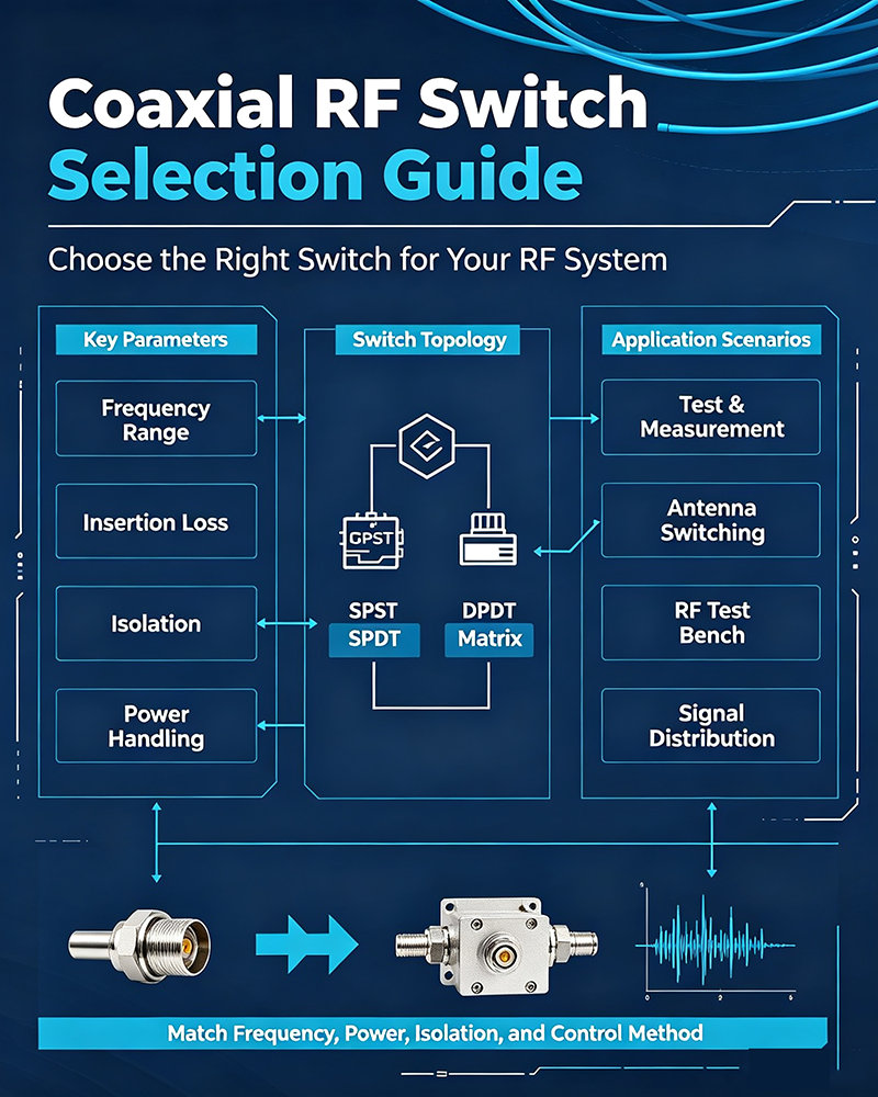
Coaxial RF Switch Selection Guide
Step 1: Define Frequency Requirements
Determine the operating frequency band and select appropriate connector types. Higher frequencies require precision connectors and tighter tolerances.
Step 2: Calculate Power Requirements
Determine CW power, peak power, and average power. Select switches with appropriate derating (typically 50-75% of rated power) for reliable long-term operation.
Step 3: Choose Configuration
Select the appropriate switch topology (SPDT, DPDT, transfer, etc.) based on your signal routing requirements. Consider latching vs. failsafe actuators for your application.
Step 4: Verify Performance Specifications
Check insertion loss, isolation, VSWR, and switching speed against your system requirements. Pay attention to specifications across the entire operating frequency band.
Step 5: Consider Environmental Factors
Account for operating temperature, humidity, vibration, and altitude. Select switches with appropriate ratings for your deployment environment.
Step 6: Evaluate Control Requirements
Choose switches with compatible control voltage and position indicator outputs for your system. Consider remote control capabilities if needed.
Frequently Asked Questions
Conclusion
Coaxial RF switches are essential components that provide reliable signal routing across a wide range of RF and microwave applications. Their standardized connectors, excellent RF performance, and proven electromechanical design make them the preferred choice for test equipment, base stations, satellite communications, and broadcast systems.
Understanding the different types, connector options, and key specifications enables you to select the right coaxial switch for your specific application. While not as fast as solid-state alternatives, coaxial switches deliver superior isolation and power handling for demanding applications.
As wireless systems continue to evolve, coaxial RF switches remain fundamental building blocks in RF infrastructure. Their combination of standardized interfaces, reliable performance, and proven technology ensures they will continue serving critical signal routing functions for many years to come.
Need Help Selecting a Coaxial RF Switch?
Our engineering team can help you choose the right coaxial RF switch for your frequency, power, and configuration requirements.
Contact Our Technical Team