

























Complete guide to RF coaxial connectors: SMA, BNC, N-type, TNC and more. Compare types, frequencies, impedance and applications with our selection chart.
Sep 15 ,26


5G communication testing, wireless terminal automated testing
Aerospace communication systems
Precision measurement equipment, radio frequency signal control of radar transmitters
Communication and navigation systems
Optical communication module-related testing
Interconnection of wireless communication base stations
An SMA connector, short for SubMiniature version A connector, is a compact threaded coaxial RF connector widely used for transmitting high-frequency signals. SMA connectors are found in RF and microwave systems, wireless communication equipment, antennas, test instruments, aerospace electronics, radar systems, and many other applications where reliable signal transmission is essential.
Although the SMA connector is physically small, its role in high-frequency systems is significant. A properly selected connector can help maintain impedance matching, reduce signal loss, control reflections, and provide a stable mechanical connection. Understanding how SMA connectors work, their specifications, types, advantages, limitations, and applications can help engineers choose the right RF connector for a specific system.
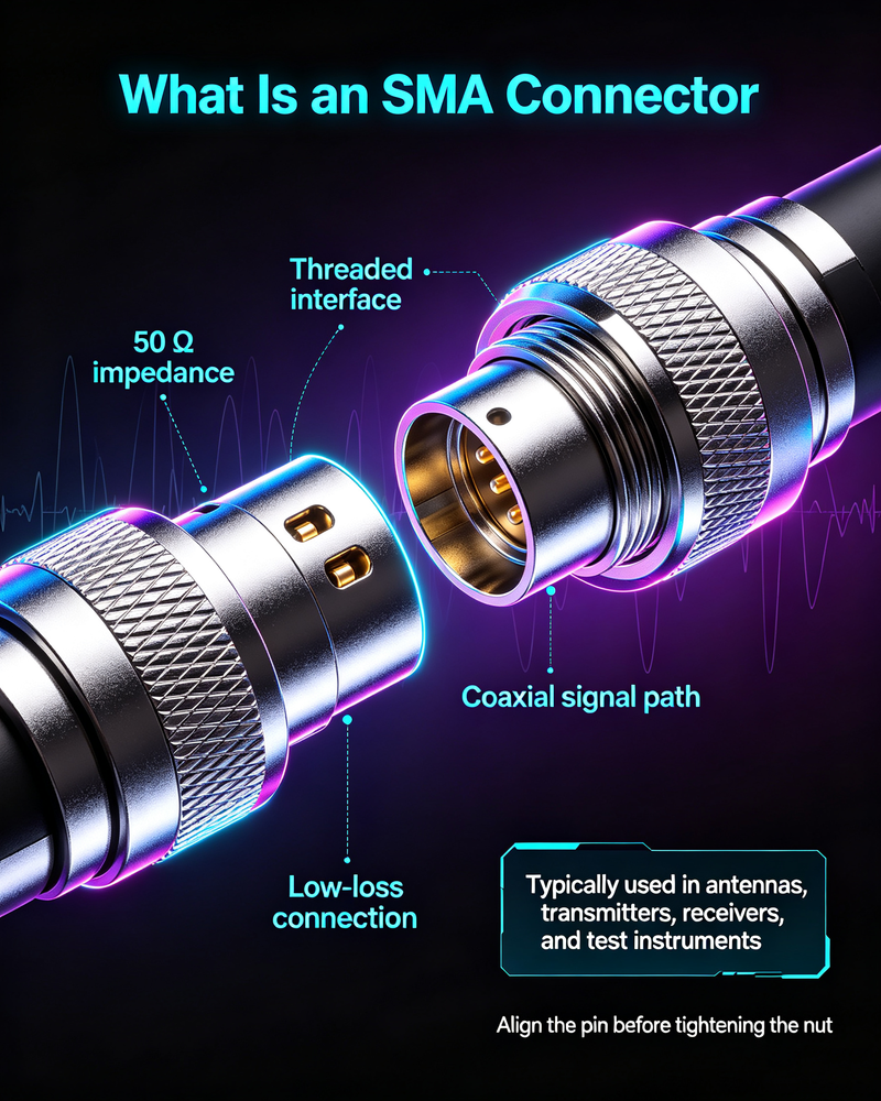
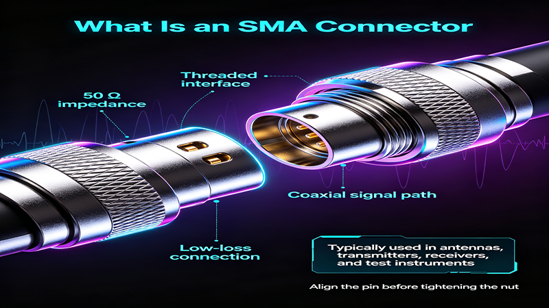
An SMA connector is a 50-ohm coaxial connector that uses a threaded coupling mechanism to create a secure connection between RF components and cables. It was originally developed for high-frequency microwave applications and has become one of the most widely recognized connector families in the RF industry.
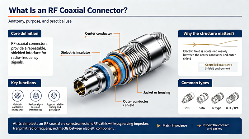
The connector typically consists of an outer conductor, dielectric insulator, center conductor, and threaded coupling interface. Its threaded design provides better mechanical stability than many push-on connector types, making it suitable for applications involving vibration, repeated testing, or demanding operating conditions.
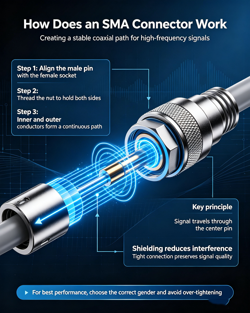
An SMA connector works by maintaining a continuous coaxial transmission path between two connected RF components. When the male and female interfaces are properly mated, the center conductors make electrical contact while the outer conductors form the ground or return path.
The internal geometry of the connector is designed to maintain a characteristic impedance close to 50 ohms. This is important because impedance discontinuities can create signal reflections, increase VSWR, and reduce overall RF system performance.
The threaded coupling nut secures the connection mechanically. Compared with push-on RF connectors, this threaded interface provides a more stable connection and helps reduce accidental disconnection.
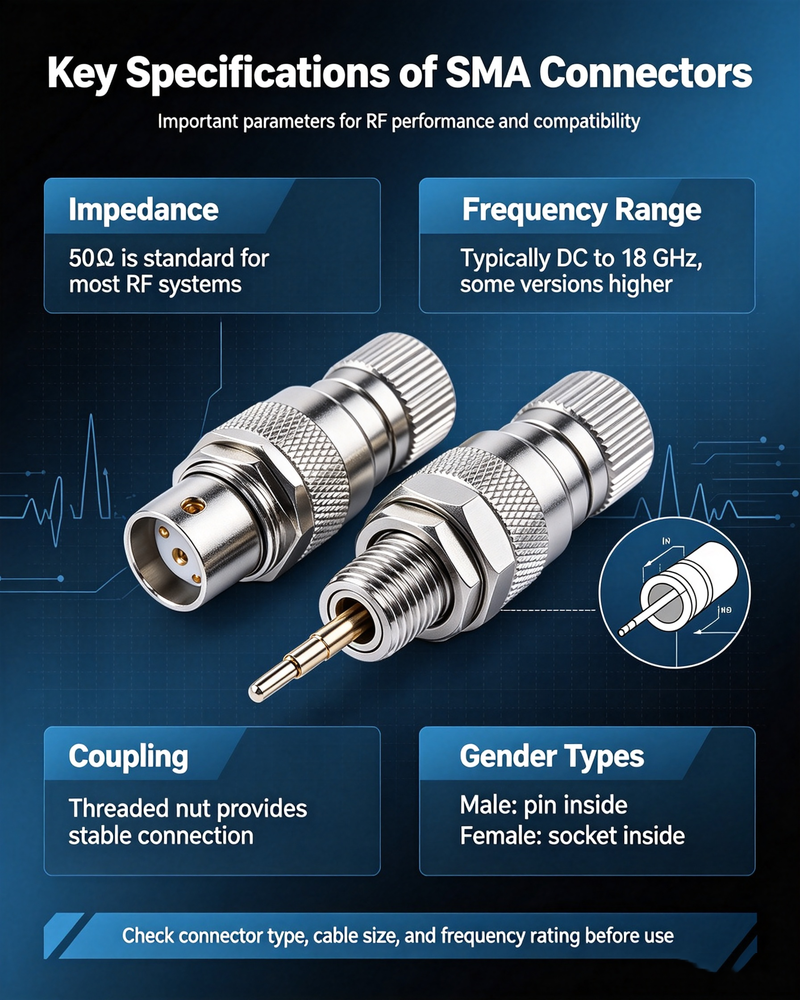
| Specification | Typical SMA Characteristics |
|---|---|
| Characteristic Impedance | 50 ohms |
| Coupling Mechanism | Threaded coupling |
| Typical Operating Frequency | DC to 18 GHz for standard SMA designs |
| Extended Frequency Versions | Higher frequencies available with precision or compatible connector designs |
| Connector Size | Compact and subminiature |
| Common Applications | RF, microwave, antennas, testing, wireless communication and instrumentation |
It is important to note that actual performance depends on the specific connector design, material quality, cable type, assembly method, and operating environment. Engineers should always check the manufacturer's datasheet when selecting a connector for a critical RF application.
Most SMA connectors are designed for 50-ohm RF systems. Impedance matching is one of the most important principles in RF engineering because mismatched impedances can cause part of the transmitted signal energy to be reflected back toward the source.
Proper impedance matching can help achieve:
For this reason, an SMA connector should be selected as part of the complete transmission system rather than as an isolated mechanical component.
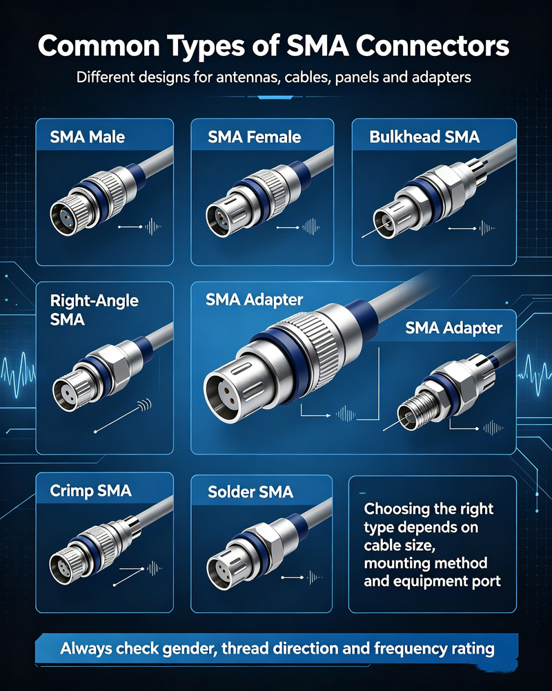
SMA connectors are available in several configurations to support different cables, mounting methods, and equipment designs.
The SMA male connector typically includes a coupling nut with internal threads and a center contact pin. It is commonly installed on RF cables, adapters, and test assemblies.
The SMA female connector generally has external threads and a center contact receptacle. It is commonly used on RF equipment panels, PCBs, and devices.
Panel-mount connectors are designed to be installed through an enclosure or equipment panel, providing a stable external RF interface.
PCB-mounted SMA connectors provide an interface between a printed circuit board and an external RF cable or test instrument.
Cable connectors are designed for coaxial cables and may use crimp, clamp, solder, or other attachment methods depending on the cable construction.
Right-angle designs are useful when installation space is limited or when the cable must be routed parallel to the equipment surface.
Understanding SMA connector gender is important when connecting RF components. In conventional terminology, the standard male SMA interface has a center pin, while the standard female interface has a center receptacle.
However, RF connectors can also be available in reverse-polarity configurations, such as RP-SMA. These connectors may have a mechanical interface similar to SMA but use a reversed center-contact arrangement. Standard SMA and RP-SMA should not be treated as interchangeable without checking the exact connector interface.
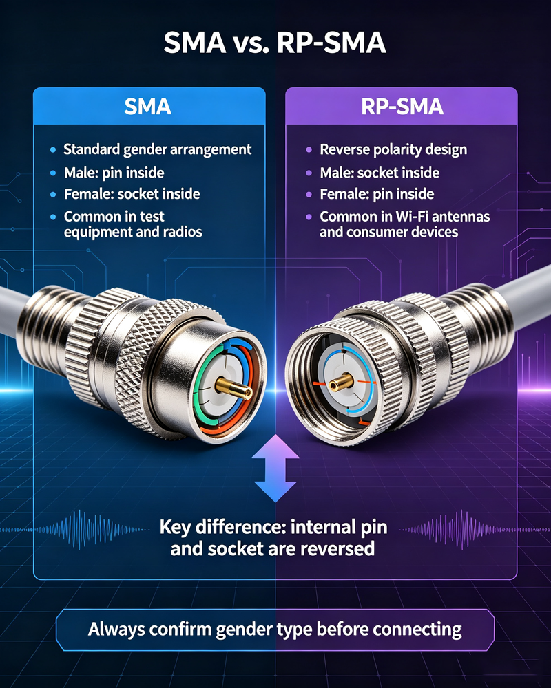
Standard SMA and RP-SMA connectors may look similar from the outside, but their center-contact arrangements are different. RP-SMA was developed with a reverse-polarity interface and is commonly encountered in certain wireless networking equipment.
| Feature | Standard SMA | RP-SMA |
|---|---|---|
| Mechanical Family | SMA-type threaded interface | Similar threaded interface |
| Center Contact Arrangement | Standard SMA configuration | Reverse-polarity configuration |
| Interchangeability | Depends on mating interface | Not automatically compatible with standard SMA |
| Common Use | General RF and microwave systems | Certain wireless and networking equipment |
When selecting a connector, visual inspection alone may not be sufficient. Always confirm the exact product specification.
Standard SMA connectors are commonly specified for frequencies up to approximately 18 GHz. However, the practical frequency range depends on the connector design and performance requirements.
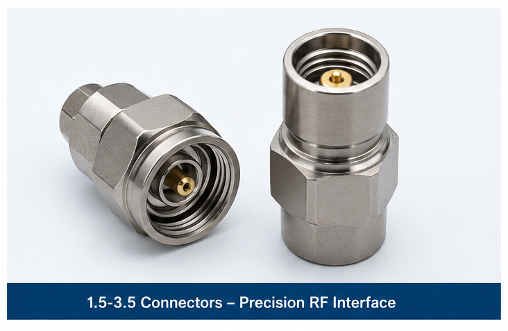
Some precision interfaces and related high-frequency connector designs can operate beyond the standard SMA frequency range. At higher frequencies, factors such as dimensional tolerances, interface quality, mating conditions, and signal integrity become increasingly important.
For applications operating above the normal SMA range, engineers may consider precision connector families designed specifically for higher-frequency microwave and millimeter-wave systems.
Despite their many advantages, SMA connectors also have limitations that should be considered.
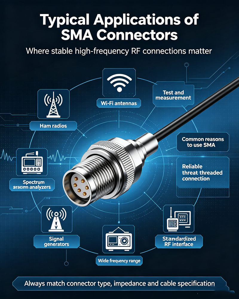
SMA connectors are commonly used to connect RF components such as amplifiers, filters, attenuators, couplers, switches, power dividers, and other microwave devices.
Many antennas and wireless devices use SMA or related connector interfaces to connect external antennas, RF modules, and communication equipment.
Laboratory instruments and test setups frequently use SMA connectors because they provide a compact and reliable threaded RF interface.
RF and microwave systems used in radar, aerospace, and defense applications often require compact connectors capable of reliable performance under demanding conditions.
Compact wireless modules, development boards, GPS systems, and IoT equipment may use SMA connectors to provide an external antenna connection.
SMA connectors are also used in industrial automation, sensing, wireless monitoring, instrumentation, and specialized communication systems.
Selecting the correct SMA connector requires more than simply choosing a male or female interface. Several technical factors should be evaluated.
Check the maximum operating frequency of the system and ensure the connector is specified for that frequency range.
The connector must match the physical dimensions and electrical characteristics of the coaxial cable. Different cable families require different connector designs.
Choose between cable-mount, panel-mount, PCB-mount, bulkhead, straight, or right-angle configurations based on the mechanical design.
For high-power RF applications, verify the connector's power rating under the expected operating frequency and environmental conditions.
Low VSWR and good return loss are important for minimizing reflections and maintaining signal integrity.
Connector insertion loss becomes increasingly important at higher frequencies and in systems with multiple interconnected components.
Consider temperature, humidity, vibration, corrosion resistance, and installation environment when selecting connector materials and finishes.
If a connector will be frequently connected and disconnected, select a design suitable for the expected number of mating cycles.
Correct installation helps maintain RF performance and prevents connector damage.
Using the correct torque is especially important in precision RF applications. Under-tightening may result in poor electrical contact, while over-tightening can damage the connector.
High VSWR can result from poor mating, damaged interfaces, incorrect connector types, cable assembly problems, or impedance discontinuities.
Excessive insertion loss may be caused by poor connector quality, contamination, damaged center contacts, incorrect cable assembly, or operation outside the intended frequency range.
A loose threaded connection can reduce mechanical stability and negatively affect RF performance. Proper tightening is essential.
Cross-threading or repeated improper installation can damage the connector interface and prevent correct mating.
Misalignment or incorrect connector mating can damage the center contact. Inspect connectors before use, especially in precision measurement systems.
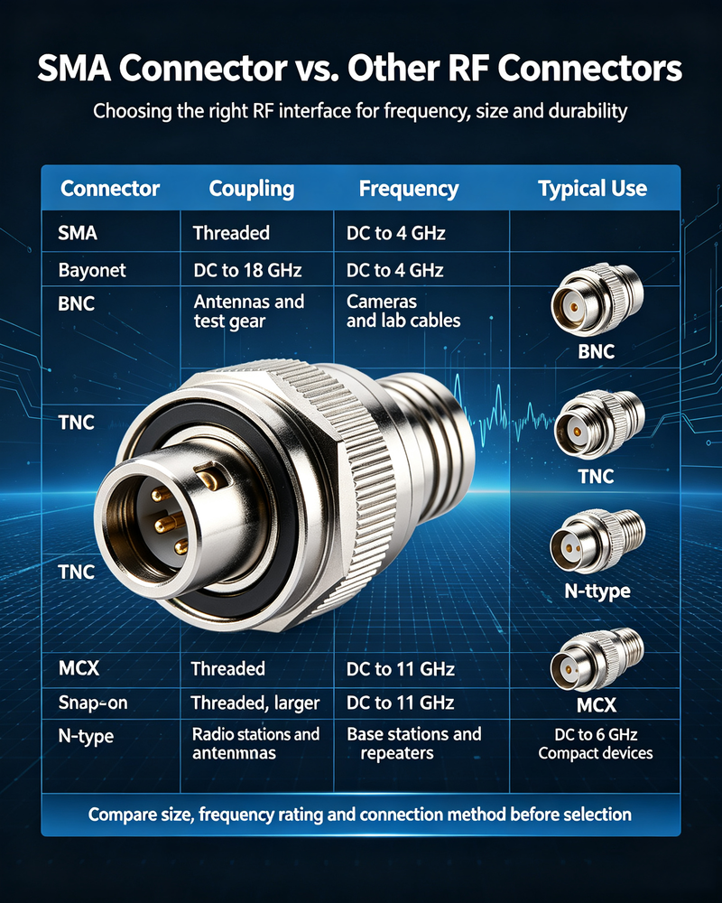
SMA connectors are often compared with other common RF connector types.
| Connector Type | General Characteristics | Typical Use |
|---|---|---|
| SMA | Compact, threaded, 50 ohms, high-frequency capable | RF, microwave, antennas and testing |
| BNC | Bayonet coupling, quick connection | Lower-frequency RF and test applications |
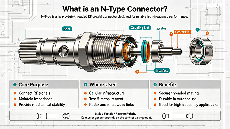
| N-Type | Larger threaded connector, robust construction | Outdoor, high-power and RF infrastructure |
| TNC | Threaded connector related to BNC family | RF applications requiring better vibration resistance |
| 2.92 mm / K-Type | Precision high-frequency connector | Higher-frequency microwave measurements |
The best connector depends on frequency, power, size, environmental requirements, cost, and system architecture.
Proper maintenance can extend connector life and help maintain consistent RF performance.
SMA stands for SubMiniature version A. It refers to a compact threaded coaxial RF connector family widely used in 50-ohm RF and microwave systems.
Standard SMA connectors are generally designed as 50-ohm connectors. However, engineers should always verify the specifications of a particular product.
Standard SMA connectors are commonly used up to approximately 18 GHz, although frequency capability depends on the specific connector design and performance requirements.
Standard SMA and RP-SMA use different center-contact arrangements and should not be assumed to be compatible. Always verify the exact interface before mating.
Yes. SMA connectors are widely used for antenna connections in wireless communication, RF modules, test systems, IoT devices, and other equipment.
Proper torque helps ensure consistent mechanical contact and RF performance while reducing the risk of connector damage caused by over-tightening or under-tightening.
An SMA connector is one of the most important and widely used connectors in RF and microwave engineering. Its compact size, threaded coupling mechanism, 50-ohm impedance, and strong high-frequency performance make it suitable for antennas, wireless systems, RF components, microwave equipment, test instruments, and industrial applications.
When choosing an SMA connector, engineers should consider operating frequency, cable compatibility, mounting style, power handling, VSWR, insertion loss, environmental requirements, and connector durability. Correct connector selection and proper installation are essential for achieving reliable RF performance and minimizing signal degradation.
For modern RF and microwave systems, the SMA connector remains a practical and versatile solution. Understanding its structure, types, limitations, and application requirements can help designers build more reliable and efficient high-frequency signal paths.


High-tech Enterprise, Feifeng Talent
Chief Engineer Wang graduated with a master's degree in high-power microwave from the Institute of Electronics, University of Chinese Academy of Sciences.
View Full Profile