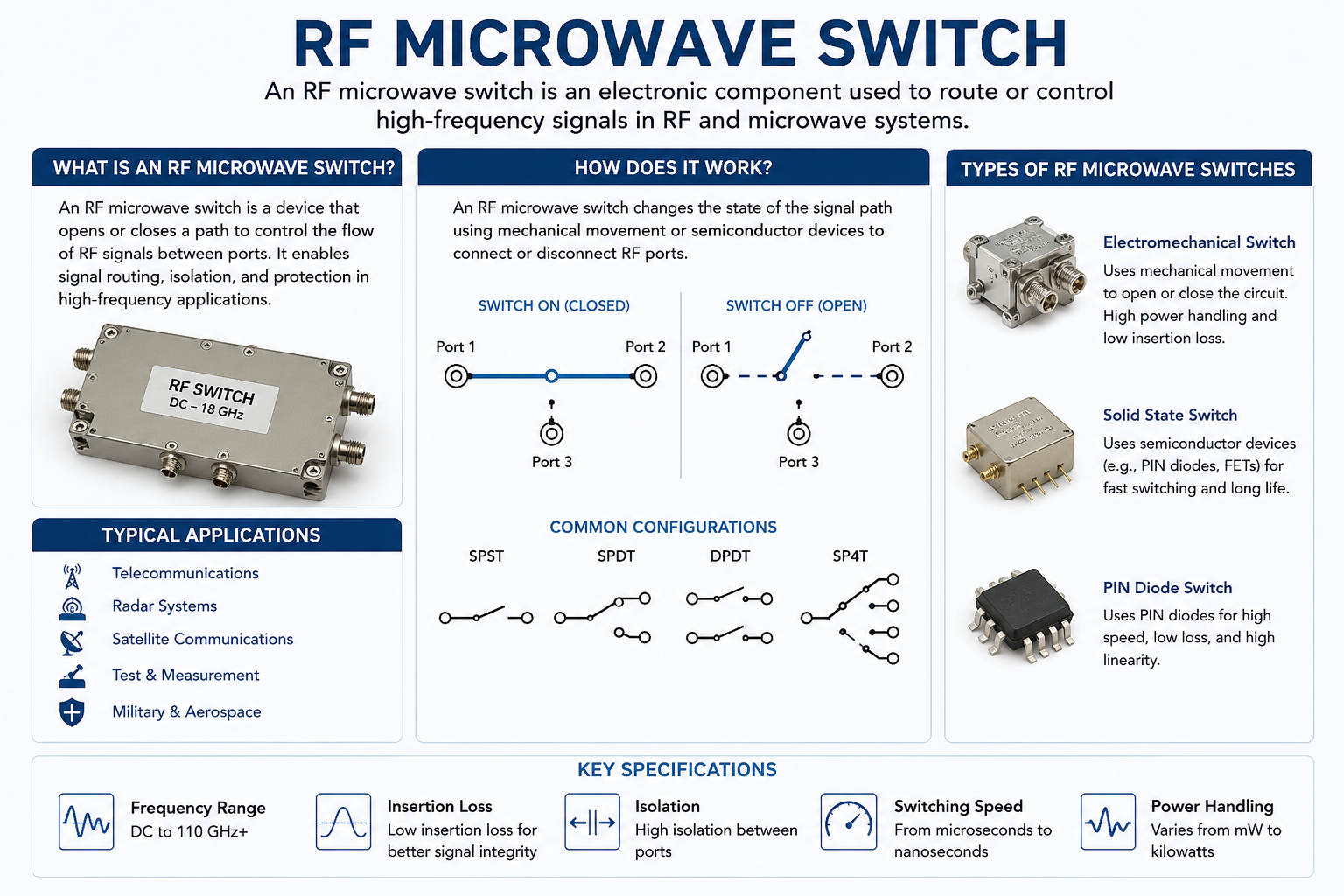
Microwave switches are essential components in modern RF and wireless systems, operating at frequencies from 1 GHz to 300 GHz. They enable critical signal routing functions in radar, satellite communications, test equipment, and emerging 5G/6G applications. This guide provides a comprehensive overview of microwave switch technologies, specifications, and applications.
What is a Microwave Switch?
Definition
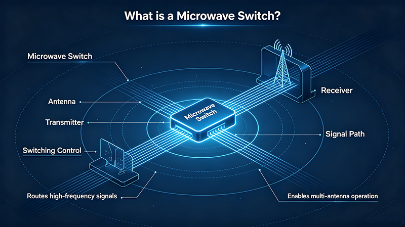
A microwave switch is an electronic component designed to route high-frequency signals in the microwave frequency range (typically 1 GHz to 300 GHz). These switches control signal paths with minimal loss, high isolation, and precise impedance matching to maintain signal integrity at microwave frequencies.
Microwave switches serve critical functions in systems where traditional RF switches cannot maintain performance. At microwave frequencies, signal wavelengths become small enough that physical component dimensions significantly affect electrical characteristics. Microwave switches are specifically engineered to handle these unique challenges through specialized materials, precision manufacturing, and optimized circuit topologies.
These switches are distinguished from lower-frequency RF switches by their ability to operate with low loss and high isolation at frequencies where parasitic capacitances, inductance, and skin effect losses become significant design challenges.
Why Microwave Switches Are Special
- Frequency Range: Operate from 1 GHz to 300 GHz, covering radar, satellite, and mmWave bands
- Precision Required: Tight tolerances necessary for proper impedance matching
- Special Materials: Often use specialized substrates and conductors
- Connector Types: SMA, 2.92mm, 2.4mm, 1.85mm, and waveguide interfaces
- Applications: Critical for high-frequency radar, satellite, and 5G mmWave systems
Types of Microwave Switches
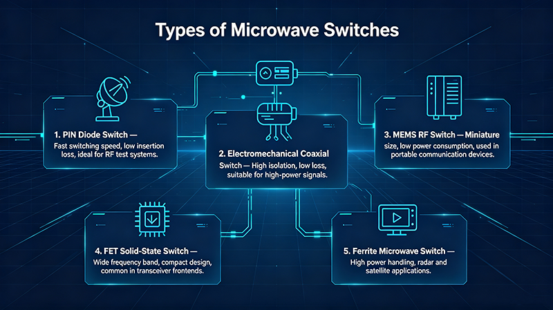
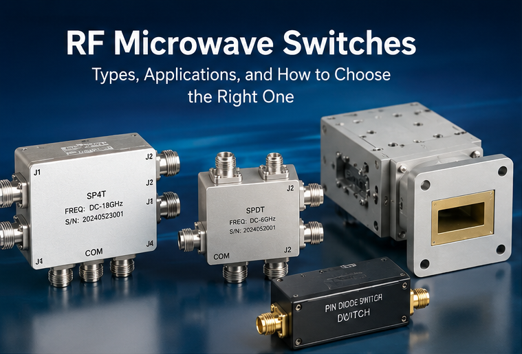
Microwave switches come in several distinct types, each optimized for specific applications and frequency ranges.
Electromechanical Microwave Switches
Use electromagnetic actuators to physically move RF contacts in coaxial or waveguide structures. Offer excellent isolation and power handling for high-frequency applications.
Solid-State Microwave Switches
Use semiconductor devices (PIN diodes, FETs) for fast, reliable switching. Ideal for high-speed applications and integration with other semiconductor circuits.
PIN Diode Microwave Switches
Specialized solid-state switches using PIN diodes. Excellent for high-frequency applications requiring fast switching and good linearity.
RF MEMS Microwave Switches
Micro-electromechanical systems offering near-zero power consumption, excellent linearity, and performance approaching electromechanical with solid-state reliability.
Waveguide Microwave Switches
Use hollow metal waveguide structures for highest power and lowest loss at microwave frequencies. Common in radar and high-power applications.
Coaxial Microwave Switches
Electromechanical switches with coaxial connectors. Provide excellent performance with easy integration into test and measurement systems.
Technology Comparison
| Technology | Frequency Range | Speed | Isolation | Best Application |
|---|---|---|---|---|
| Electromechanical | DC - 67 GHz | 5-15 ms | 60-90 dB | High power, test |
| Solid-State (PIN) | 100 MHz - 50 GHz | 1-100 ns | 30-60 dB | Radar, fast switching |
| Solid-State (FET) | DC - 40 GHz | 1-10 ns | 40-60 dB | Mobile, integrated |
| RF MEMS | DC - 100 GHz | 1-10 us | 50-80 dB | High-frequency, low loss |
| Waveguide | 1 - 300 GHz | 50-200 ms | 60-100 dB | Highest power, radar |
Key Microwave Switch Specifications
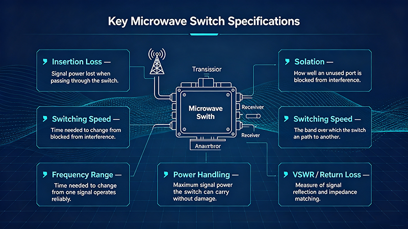
Understanding microwave switch specifications is crucial for selecting the right component for your application.
Primary Specifications
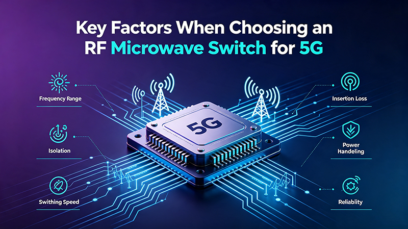
1. Frequency Range
Defines the operating frequency band. Microwave switches typically cover specific bands (L, S, C, X, Ku, K, Ka, V, W bands) or broadband ranges. Verify specifications across the entire frequency band, not just at the center frequency.
2. Insertion Loss
Signal power loss in the ON state. Critical for microwave systems where loss directly impacts system noise figure and link budget. Premium switches achieve 0.2-0.5 dB; typical values range from 0.3-2.0 dB depending on frequency and technology.
3. Isolation
Signal blocking capability in the OFF state. Higher isolation prevents signal leakage and interference. Microwave switches typically provide 40-90 dB, with waveguide switches achieving the highest values.
4. VSWR (Voltage Standing Wave Ratio)
Measures impedance matching quality. Lower VSWR (closer to 1:1) means better matching and less signal reflection. Microwave switches typically specify VSWR < 1.5:1 for good performance.
5. Power Handling
Maximum RF power the switch can handle. Critical for transmitter applications. Specified separately for CW (continuous) and peak power. Waveguide switches handle highest powers (kW range); solid-state switches typically lower.
6. Switching Speed
Time to change states. Measured from control signal to stable RF output. Critical for radar, TDD, and frequency-hopping applications where microsecond or nanosecond switching is required.
7. Connector Type
Physical interface to system. Common microwave connectors include SMA (up to 27 GHz), 2.92mm (40 GHz), 2.4mm (50 GHz), 1.85mm (67 GHz), and waveguide flanges for highest frequencies.
Secondary Specifications
- IP3 (Third-Order Intercept Point): Linearity measure for intermodulation performance
- P1dB (1dB Compression Point): Indicates compression onset
- Repeatability: Switch-to-switch and cycle-to-cycle consistency
- Operating Lifetime: Number of switching cycles before failure
- Control Interface: TTL, CMOS, or other logic levels for switching control
- Temperature Range: Operating temperature specifications
Common Applications
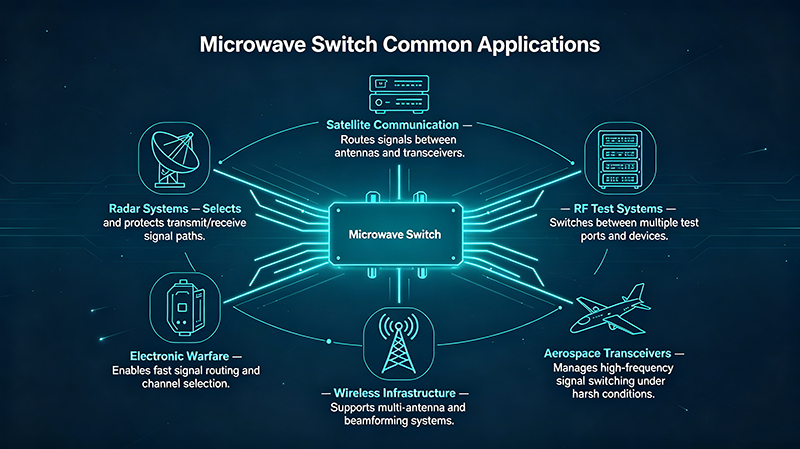
Microwave switches are critical components in numerous high-frequency applications across defense, telecommunications, and scientific research.
Radar Systems
Phased array radars use thousands of microwave switches in T/R modules for beam steering. Military, weather, and automotive radars rely on these switches for fast, reliable operation.
Satellite Communications
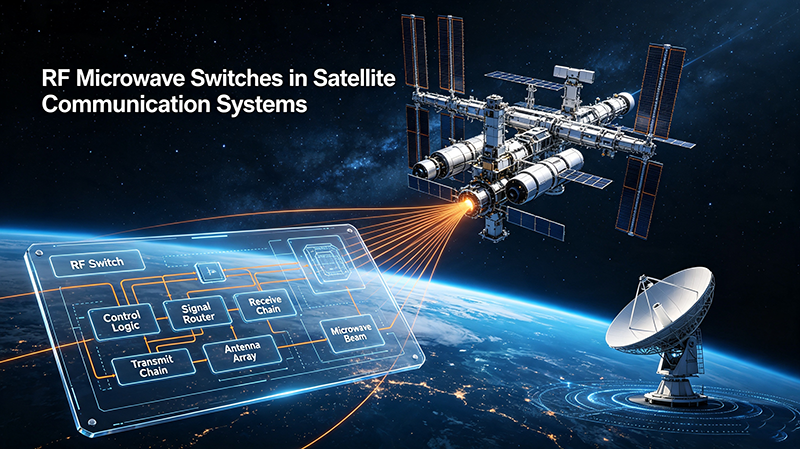
Ground stations and satellite transponders use microwave switches for redundancy, polarization selection, and signal routing. Critical for maintaining communication links.
5G mmWave Networks
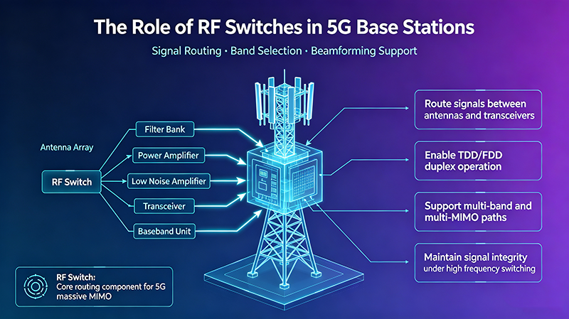
mmWave 5G base stations and user equipment require microwave switches for beamforming and signal routing at 24-40 GHz frequencies.
Test and Measurement
Network analyzers, spectrum analyzers, and automated test systems use microwave switches for multi-port measurements and signal routing.
Electronic Warfare
EW systems use microwave switches for threat detection, frequency hopping, and countermeasures. Fast switching enables rapid response to changing threats.
Aerospace and Defense
Avionics, missile guidance, and space systems use microwave switches for signal routing in mission-critical applications with extreme reliability requirements.
Medical Imaging
MRI systems and medical imaging equipment use microwave switches for signal routing in diagnostic applications requiring high reliability.
Scientific Research
Radio astronomy, particle accelerators, and research instruments use specialized microwave switches for sensitive measurement applications.
Emerging Application: 6G Research
Research into 6G communications at sub-THz frequencies (140-300 GHz) is driving development of next-generation microwave switches with even higher frequency capability, lower loss, and improved integration.
Advantages and Trade-offs
Electromechanical vs Solid-State Microwave Switches
Electromechanical Advantages
- Superior isolation (60-100 dB)
- Highest power handling
- Lowest insertion loss
- DC to high frequency coverage
- Better linearity
- Long shelf life
Solid-State Advantages
- Sub-microsecond switching
- Unlimited switching cycles
- Silent operation
- Compact and lightweight
- Low power consumption
- No moving parts
- High reliability
Common Microwave Switch Trade-offs
| Trade-off | Description | Mitigation |
|---|---|---|
| Speed vs Power | Faster switches typically handle less power | Use solid-state for low power, electromechanical for high power |
| Frequency vs Cost | Higher frequency switches cost significantly more | Use lowest frequency that meets requirements |
| Isolation vs Size | Higher isolation requires larger switch structures | Choose based on application priority |
| Bandwidth vs Performance | Wider bandwidth often means compromised peak performance | Match bandwidth to actual application needs |
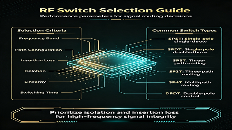
Microwave Switch Selection Guide
Step 1: Define Your Requirements
- Operating frequency range (specific bands or broadband)
- Power handling requirements (CW and peak)
- Switching speed needs
- Isolation requirements
- Insertion loss budget
- Connector types and interface requirements
- Environmental conditions
- Reliability and lifetime requirements
Step 2: Choose Technology
Technology Selection Guidelines
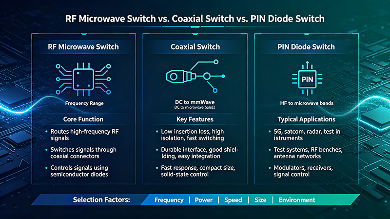
- Electromechanical: Best for high power, high isolation, test applications, infrequent switching
- PIN Diode: Best for fast switching, radar, frequent operation, moderate power
- FET Solid-State: Best for integration, mobile devices, low power consumption
- RF MEMS: Best for premium performance, high frequency, low loss requirements
- Waveguide: Best for highest power and frequency applications
Step 3: Verify Specifications
Check that the switch meets or exceeds all your requirements with appropriate safety margins. Pay special attention to frequency-dependent parameters and temperature variations.
Step 4: Consider Practical Factors
- Cost vs Performance: Balance budget against requirements
- Size and Weight: Critical for portable and aerospace applications
- Power Consumption: Important for battery-powered systems
- Control Interface: Compatibility with your control system
- Availability: Lead times and long-term supply
- Support: Manufacturer technical support and documentation
Frequently Asked Questions
Conclusion
Microwave switches are critical components that enable the high-frequency signal routing required in modern radar, satellite, 5G, and defense systems. Understanding the different technologies—electromechanical, solid-state, RF MEMS, and waveguide—helps you select the optimal switch for your specific application requirements.
Key selection criteria include frequency range, power handling, switching speed, isolation, and insertion loss. Each technology offers distinct advantages: electromechanical for high power and isolation, solid-state for speed and reliability, RF MEMS for premium performance, and waveguide for the highest frequencies and powers.
As wireless systems continue evolving toward higher frequencies with 5G mmWave, 6G research, and advanced radar applications, microwave switches will remain essential building blocks. Selecting the right switch technology and specifications ensures optimal system performance, reliability, and value for your application needs.
Need Help with Microwave Switch Selection?
Our technical team can help you evaluate microwave switch options and select the optimal component for your specific application.
Contact Our Technical Team