




























RF Switch Insertion Loss: How to Minimize Signal Degradation
RF switch insertion loss is one of the most important performance parameters in modern microwave and wireless systems. Whether used in radar, satellite communication, 5G networks, test equipment, or electronic warfare systems, an RF switch with excessive insertion loss can significantly reduce signal quality, system sensitivity, and overall efficiency.
Understanding the causes of RF switch insertion loss and learning how to minimize signal degradation helps engineers select the right RF microwave switch, improve system performance, and maintain reliable high-frequency signal transmission.
What Is RF Switch Insertion Loss?
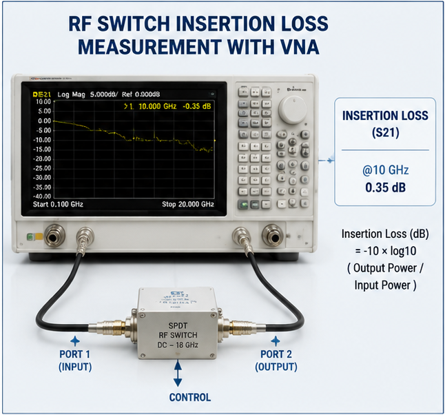
Insertion loss refers to the amount of signal power lost when an RF switch is inserted into a transmission path. It is typically measured in decibels (dB) and represents the difference between the input power and output power.
Insertion Loss Formula:
Insertion Loss (dB) = -10 × log10(Output Power / Input Power)
For example, if an RF switch receives a 10 dBm input signal and outputs 8 dBm, the insertion loss is approximately 2 dB.
In high-frequency applications, even small insertion losses can create noticeable performance degradation, especially in systems requiring high sensitivity and low noise levels.
Why Does RF Switch Insertion Loss Matter?
A high-performance RF system depends on maintaining signal integrity throughout the entire signal chain. RF switch insertion loss directly impacts:
- Signal strength: Higher loss reduces available RF power at the receiver.
- Noise performance: Additional loss before amplification increases system noise figure.
- Transmission range: Lower output power limits communication distance.
- Measurement accuracy: Test systems require minimal signal distortion.
- System efficiency: Excessive loss increases power consumption.
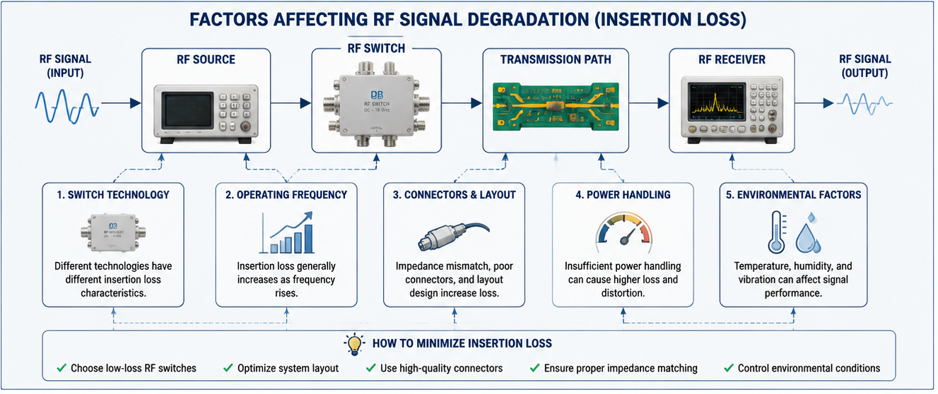
Main Factors Affecting RF Switch Insertion Loss
1. Switch Technology
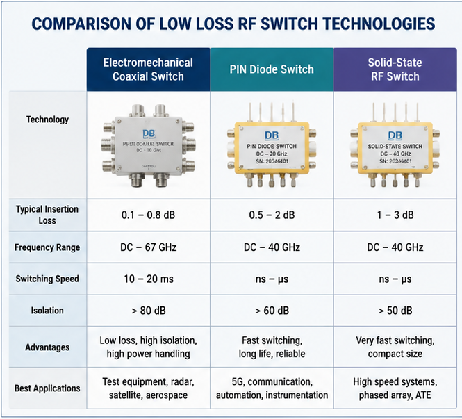
Different RF switch technologies have different insertion loss characteristics.
| RF Switch Type | Typical Insertion Loss | Advantages |
|---|---|---|
| Electromechanical Coaxial Switch | 0.1 - 0.8 dB | Excellent isolation and low loss |
| PIN Diode Switch | 0.5 - 2 dB | Fast switching speed and high reliability |
| Solid-State RF Switch | 1 - 3 dB | Compact size and high switching speed |
2. Operating Frequency
Insertion loss generally increases as operating frequency rises. At microwave and millimeter-wave frequencies, transmission line effects, connector quality, and material characteristics become increasingly important.
For example, an RF switch operating at 6 GHz may have significantly lower loss than the same switch operating near 40 GHz or 67 GHz.
3. RF Connector and Transmission Line Design
Poor connector selection or improper PCB layout can introduce additional losses. Common causes include:
- Impedance mismatch
- Poor return loss performance
- Incorrect transmission line dimensions
- Low-quality RF connectors
4. Power Handling Requirements
High-power RF applications require switches designed with appropriate materials and structures. Insufficient power handling capability can increase signal distortion and long-term degradation.
How to Minimize RF Switch Insertion Loss
1. Select a Low-Loss RF Switch
Choosing the correct RF switch technology is the first step in minimizing signal degradation. For applications requiring maximum signal integrity, low insertion loss coaxial switches are often preferred.
When selecting a switch, consider:
- Frequency range
- Insertion loss specification
- Isolation requirement
- Switching speed
- Power handling capability
2. Optimize RF System Layout
Proper RF layout design can significantly reduce additional signal loss. Engineers should:
- Keep RF paths short
- Maintain 50-ohm impedance matching
- Avoid unnecessary bends
- Use high-quality connectors
- Minimize transitions between transmission structures
3. Improve Connector Selection
RF connectors play a critical role in maintaining signal quality. High-frequency systems often use precision connectors such as:
- SMA connectors
- 2.92 mm connectors
- 2.4 mm connectors
- 1.85 mm connectors
4. Consider Temperature and Environmental Effects
Temperature changes can affect conductor resistance, dielectric properties, and mechanical alignment, resulting in increased insertion loss.
For aerospace, defense, and outdoor communication systems, temperature-compensated RF switches provide better long-term stability.
RF Switch Insertion Loss Testing Methods
Accurate measurement is essential for verifying RF switch performance. Common testing methods include:
- Vector Network Analyzer (VNA): Measures insertion loss, return loss, and isolation.
- Calibration Techniques: Removes cable and connector errors.
- Frequency Sweep Testing: Evaluates performance across the operating bandwidth.
Choosing the Right RF Microwave Switch
When selecting an RF microwave switch, engineers should balance insertion loss with other important specifications. A low-loss switch is not always the best choice if it cannot meet isolation, power handling, or switching speed requirements.
Key specifications to compare include:
- Insertion loss (dB)
- Isolation (dB)
- Frequency range (GHz)
- VSWR
- Switching time
- Operating temperature range
Conclusion
RF switch insertion loss is a critical factor affecting signal quality in microwave and wireless systems. By selecting the appropriate RF switch technology, optimizing system design, using high-quality connectors, and performing accurate measurements, engineers can significantly reduce signal degradation.
For applications requiring high reliability and superior RF performance, low-loss coaxial switches and advanced microwave switching solutions provide the best balance between signal integrity, durability, and efficiency.
Related Keywords
- RF switch insertion loss
- Low insertion loss RF switch
- RF microwave switch
- Coaxial switch manufacturer
- PIN diode RF switch
- Microwave signal degradation
- High frequency RF switch
About the Author — MeiXun Team
Chief Engineer Wang
High-tech Enterprise, Feifeng Talent
Chief Engineer Wang graduated with a master's degree in high-power microwave from the Institute of Electronics, University of Chinese Academy of Sciences.
View Full Profile- RF Switch Circuit Diagram
- RF Switch
- Ohm's Law
- dBm to Watt
- mW to dBm
- Wavelength to Frequency
- RF Connector
- SMA Connector
- RF Switch Module
- RF Coupler
- RF PIN Switch
- Microwave Coaxial Switch
- PIN Switch
- Coaxial RF Switch
- Waveguide Switch
- Microwave Switch
- Low Noise Amplifier
- PIN Diode Switch
- Coaxial Switch
- RF Microwave Switch
- SPST Switch