


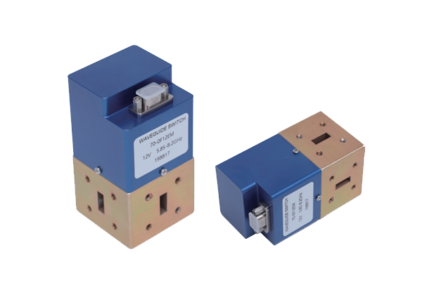
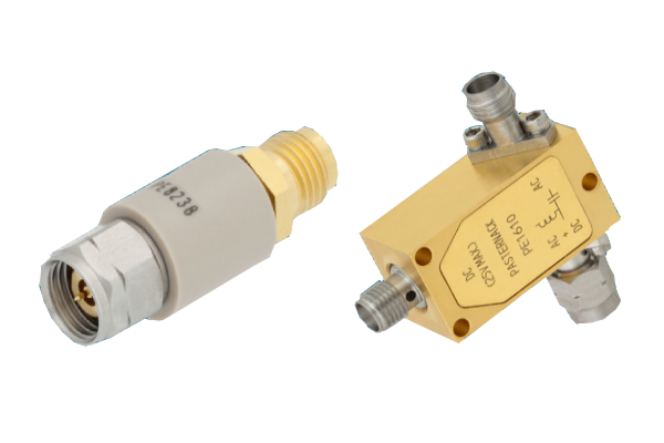
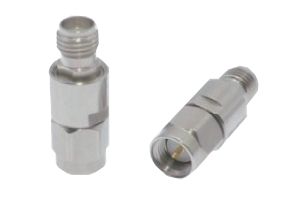
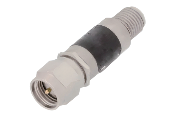
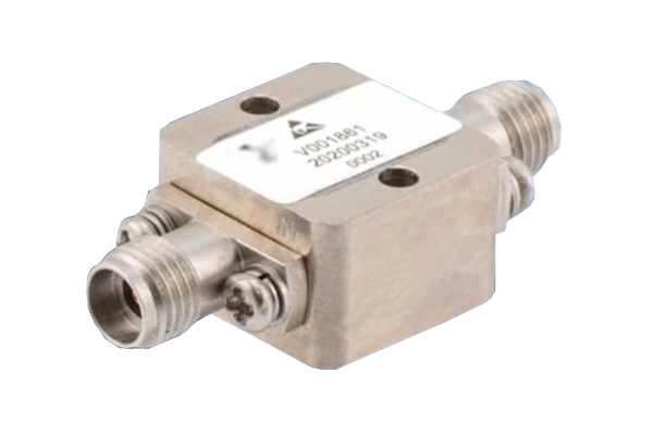




Waveguide adapters are essential microwave components used to connect different transmission media, interface standards, and RF equipment. From radar systems and satellite communications to microwave testing and aerospace applications, the right waveguide adapter ensures efficient signal transmission, reliable impedance matching, and stable high-frequency performance.
1. What Is a Waveguide Adapter?
A waveguide adapter is a passive microwave component designed to connect a waveguide to another transmission interface or microwave device. It provides a mechanical and electrical transition between different RF structures while maintaining controlled electromagnetic signal propagation.
Unlike conventional coaxial cables, which transmit electromagnetic energy through a central conductor and an outer conductor, waveguides transmit electromagnetic energy through a hollow metallic structure. Waveguide adapters provide the transition between these different transmission technologies.
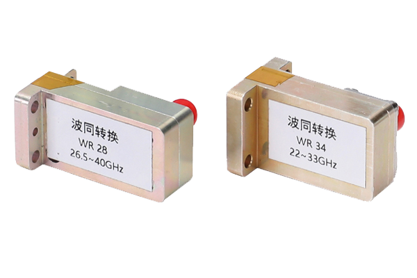
One of the most widely used configurations is the waveguide-to-coaxial adapter. It connects a rectangular waveguide to a coaxial connector such as SMA, N-type, or 2.92 mm, allowing waveguide systems to interface with RF instruments, amplifiers, switches, and coaxial transmission lines.
How Does a Waveguide Adapter Work?
A waveguide adapter operates by converting electromagnetic energy between two transmission structures. In a waveguide-to-coaxial transition, a carefully positioned probe or coupling structure is inserted into the waveguide to excite the dominant electromagnetic mode.
For standard rectangular waveguides, the dominant mode is generally TE10. The coaxial probe couples energy into or out of this mode, creating a transition between the coaxial TEM mode and the waveguide's TE10 mode.
The transition is engineered to minimize:
- Insertion loss caused by impedance mismatch and conductor losses.
- Return loss caused by unwanted reflections.
- Unwanted higher-order mode excitation.
- Signal leakage and radiation losses.
2. Main Types of Waveguide Adapters
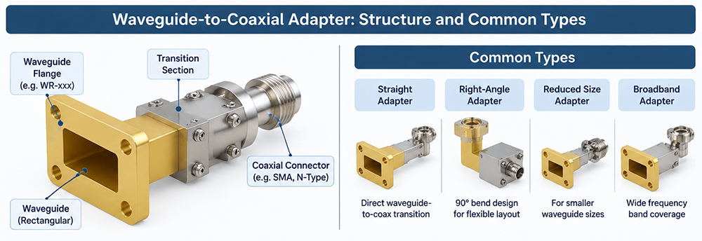
Waveguide adapters can be classified according to their interface configuration, mechanical geometry, and application requirements. Understanding these types helps engineers choose the most suitable solution for microwave system integration.
Waveguide-to-Coaxial Adapter
Converts signals between rectangular waveguides and coaxial transmission lines. Common connector options include SMA, N-type, 2.92 mm, and 2.4 mm.
Waveguide-to-Waveguide Adapter
Connects waveguides with different sizes, flange configurations, or cross-sectional dimensions. It is commonly used in microwave transmission systems.
Right-Angle Waveguide Adapter
Changes the direction of microwave signal transmission, typically by 90 degrees, helping optimize equipment layout and reduce installation space.
Waveguide Twist Adapter
Rotates the waveguide orientation to change the polarization alignment of the electromagnetic field without requiring a conventional coaxial transition.
Waveguide Transition Adapter
Provides a transition between different waveguide dimensions or transmission structures while controlling impedance and electromagnetic field distribution.
Custom Waveguide Adapter
Designed for specialized operating frequencies, mechanical interfaces, flange standards, power levels, and demanding environmental conditions.
Waveguide-to-Coaxial Adapter Types by Connector
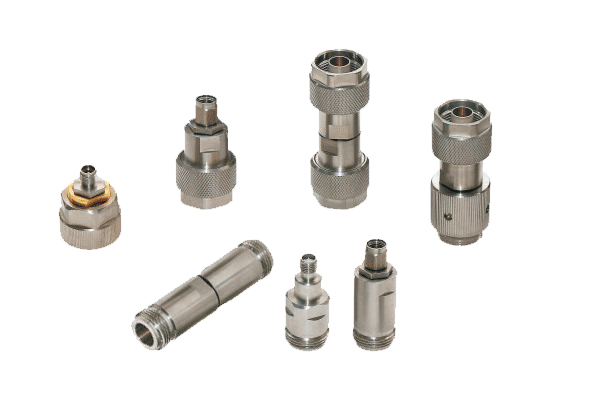
Waveguide-to-coaxial adapters are also categorized according to the coaxial connector interface. The connector determines the mechanical compatibility and influences the practical frequency range of the complete assembly.
| Coaxial Connector | Typical Application | Important Considerations |
|---|---|---|
| SMA | General RF and microwave testing | Commonly used in compact microwave systems; frequency capability depends on connector grade. |
| N-Type | RF communications and test equipment | Robust threaded interface and good mechanical durability. |
| 2.92 mm (K-Type) | High-frequency microwave applications | Designed for precision microwave measurements up to 40 GHz in suitable configurations. |
| 2.4 mm | Millimeter-wave testing | Commonly used in precision systems operating up to 50 GHz. |
| 1.85 mm | High-frequency millimeter-wave systems | Supports precision coaxial measurements up to 67 GHz in suitable configurations. |
These frequency values describe common connector interface capabilities, not guaranteed operating limits for every adapter. The actual frequency range must be verified against the manufacturer's specifications for the complete adapter assembly.
3. WR Waveguide Size Chart and Frequency Guide
WR (Waveguide Rectangular) designations are widely used to identify standard rectangular waveguide dimensions. The WR number is approximately the broad internal dimension expressed in hundredths of an inch.
For example, WR-90 has a broad internal dimension of approximately 0.90 inches. However, the WR designation alone does not define the complete operating frequency range. The narrow internal dimension, cutoff frequency, operating mode, and design requirements must also be considered.
Common WR Waveguide Size Chart
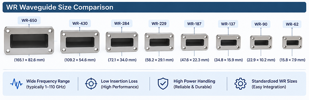
The following table summarizes commonly used rectangular waveguide sizes, their approximate internal dimensions, and typical frequency bands for dominant-mode operation.
| Waveguide Size | Broad Dimension (mm) | Narrow Dimension (mm) | Approximate Frequency Range (GHz) | Common Band |
|---|---|---|---|---|
| WR-430 | 109.22 | 54.61 | 1.70–2.60 | L/S Band |
| WR-340 | 86.36 | 43.18 | 2.20–3.30 | S Band |
| WR-284 | 72.14 | 34.04 | 2.60–3.95 | S Band |
| WR-229 | 58.17 | 29.08 | 3.30–4.90 | C Band |
| WR-187 | 47.55 | 22.15 | 3.95–5.85 | C Band |
| WR-159 | 40.39 | 20.19 | 4.64–7.05 | C Band |
| WR-137 | 34.85 | 15.80 | 5.85–8.20 | C/X Band |
| WR-112 | 28.50 | 12.62 | 7.05–10.00 | X Band |
| WR-90 | 22.86 | 10.16 | 8.20–12.40 | X Band |
| WR-75 | 19.05 | 9.525 | 10.00–15.00 | Ku Band |
| WR-62 | 15.80 | 7.90 | 12.40–18.00 | Ku Band |
| WR-51 | 12.95 | 6.48 | 15.00–22.00 | K Band |
| WR-42 | 10.67 | 4.32 | 18.00–26.50 | K Band |
| WR-34 | 8.636 | 4.318 | 22.00–33.00 | Ka Band |
| WR-28 | 7.112 | 3.556 | 26.50–40.00 | Ka Band |
| WR-22 | 5.588 | 2.845 | 33.00–50.00 | Q Band |
| WR-19 | 4.775 | 2.388 | 40.00–60.00 | V Band |
| WR-15 | 3.759 | 1.880 | 50.00–75.00 | V Band |
| WR-12 | 3.099 | 1.549 | 60.00–90.00 | W Band |
| WR-10 | 2.540 | 1.270 | 75.00–110.00 | W Band |
| WR-8 | 2.032 | 1.016 | 90.00–140.00 | Millimeter Wave |
How to Understand WR Waveguide Dimensions
Rectangular waveguide dimensions are defined by two internal measurements:
- Broad dimension (a): The wider internal wall dimension. It primarily determines the TE10 cutoff frequency.
- Narrow dimension (b): The smaller internal wall dimension. It influences field distribution, propagation characteristics, and higher-order mode behavior.
The dominant TE10 cutoff frequency is calculated using:
fc = c / (2a)
Where:
- fc = Cutoff frequency in Hz
- c = Speed of light in vacuum (approximately 3 × 10⁸ m/s)
- a = Broad internal waveguide dimension in meters
For reliable operation, the signal frequency must be above the dominant-mode cutoff frequency and below the practical upper operating limit where unwanted higher-order modes may propagate.
4. Waveguide-to-Coaxial Adapter: Structure and Design
A waveguide-to-coaxial adapter is designed to connect a rectangular waveguide directly to a coaxial RF interface. It is widely used in microwave measurement systems, antenna testing, radar equipment, and satellite communication systems.
Main Structural Components
- Waveguide body: The metallic rectangular transmission structure that supports the desired electromagnetic mode.
- Coaxial connector: Provides the external RF interface, such as SMA, N-type, or 2.92 mm.
- Coupling probe: Transfers electromagnetic energy between the coaxial and waveguide structures.
- Matching structure: Helps minimize reflections and improve impedance matching.
- Mounting flange: Provides mechanical attachment to other waveguide components.
Important Electrical Parameters
| Parameter | Definition | Why It Matters |
|---|---|---|
| Frequency Range | Specified operating frequency interval | Ensures compatibility with the microwave system. |
| Insertion Loss | Power lost during signal transmission | Lower insertion loss improves signal efficiency. |
| Return Loss | Measure of reflected signal power | Higher return loss generally indicates better matching. |
| VSWR | Voltage Standing Wave Ratio | Indicates impedance matching quality. |
| Power Handling | Maximum permissible RF power under specified conditions | Prevents overheating, arcing, and component damage. |
| Operating Temperature | Permitted environmental temperature range | Determines suitability for demanding environments. |
Insertion Loss and Return Loss
Insertion loss represents the reduction in transmitted signal power caused by the adapter. It is commonly expressed in decibels (dB). A low insertion loss is especially important in sensitive receiver systems and precision microwave measurement applications.
Return loss describes how effectively the adapter minimizes reflected power. Higher return loss values generally indicate better impedance matching.
These parameters should be evaluated across the entire specified frequency range rather than at a single test frequency.
5. How to Select the Right Waveguide Adapter
Selecting a waveguide adapter requires evaluating both electrical performance and mechanical compatibility. A mismatch in waveguide size, connector interface, or operating frequency can lead to excessive reflections, poor transmission efficiency, and system instability.
Step 1: Determine the Operating Frequency
Identify the system's minimum and maximum operating frequencies. Select a waveguide size that supports the required frequency range in its intended operating mode.
Step 2: Identify the WR Waveguide Size
Confirm the existing waveguide designation, such as WR-90, WR-75, WR-62, WR-42, or WR-28. The adapter must match the waveguide dimensions and compatible flange interface.
Step 3: Choose the Coaxial Connector
Select a coaxial connector based on frequency, mechanical requirements, cable compatibility, and test equipment interfaces.
Step 4: Evaluate Electrical Performance
Review insertion loss, return loss, VSWR, power handling, and phase characteristics where applicable. For precision applications, request measured S-parameter data.
Step 5: Verify Mechanical and Environmental Requirements
Check flange standards, mounting dimensions, material, surface finish, connector orientation, operating temperature, and environmental protection requirements.
- Operating frequency and bandwidth
- WR waveguide designation
- Coaxial connector type
- Flange standard and mounting dimensions
- Insertion loss and return loss
- Maximum input power
- Temperature and environmental conditions
- Required VSWR and phase performance
6. Applications of Waveguide Adapters
Waveguide adapters are used across a wide range of RF and microwave industries because they provide reliable transitions between waveguide and coaxial systems.
Radar and Defense Systems
Radar systems frequently use waveguide transmission structures to handle microwave signals with low transmission loss. Waveguide-to-coaxial adapters allow radar equipment to connect with RF test instruments, receivers, and signal processing modules.
Satellite Communications
Satellite communication systems operate across microwave frequency bands, including C, X, Ku, and Ka bands. Waveguide adapters provide essential interfaces for antennas, feed assemblies, amplifiers, and microwave components.
Microwave Testing and Measurement
RF laboratories use waveguide adapters to connect waveguide components to vector network analyzers, signal generators, spectrum analyzers, and other coaxial measurement equipment.
5G and Millimeter-Wave Research
Millimeter-wave testing requires precision transmission interfaces and stable RF performance. Waveguide-to-coaxial adapters are useful for evaluating high-frequency components, antenna systems, and microwave modules.
Aerospace and Navigation
Aerospace systems often require compact, lightweight, and mechanically reliable microwave components. Custom waveguide adapters can be designed to satisfy specific installation and environmental requirements.
7. Waveguide Adapter vs. Coaxial Adapter: Key Differences
Although both components provide RF connectivity, waveguide adapters and coaxial adapters serve different purposes.
| Feature | Waveguide Adapter | Coaxial Adapter |
|---|---|---|
| Transmission Structure | Hollow metallic waveguide | Inner and outer conductors |
| Transmission Mode | Typically TE10 for rectangular waveguides | TEM or quasi-TEM |
| Frequency Application | Commonly microwave and millimeter-wave systems | Broad range of RF and microwave systems |
| Power Handling | Can support high power depending on dimensions and design | Limited by connector, cable, and dielectric design |
| Interface | Waveguide flange to coaxial or waveguide interface | Coaxial connector to coaxial connector |
| Typical Use | Radar, satellite, antenna feeds, microwave testing | RF cables, instruments, amplifiers, and modules |
8. Common Waveguide Adapter Selection Mistakes
Choosing the Wrong WR Size
Different WR waveguides have different internal dimensions and operating frequency ranges. Even if two waveguides have overlapping frequency capabilities, their mechanical interfaces may not be interchangeable.
Ignoring Connector Frequency Limits
The coaxial connector must support the intended frequency range. Using an unsuitable connector can introduce excessive loss, reflections, and measurement uncertainty.
Overlooking Flange Compatibility
Waveguide flanges vary according to standards and mechanical configurations. Always verify bolt patterns, alignment features, and mating dimensions before installation.
Evaluating Only the Center Frequency
An adapter may perform well at its center frequency but exhibit degraded return loss or insertion loss near the band edges. Always review full-band performance data.
Ignoring Power and Thermal Limits
High-power microwave systems require careful evaluation of RF power handling, voltage breakdown, thermal dissipation, and environmental conditions.
9. Frequently Asked Questions About Waveguide Adapters
Q1: What is a waveguide-to-coaxial adapter used for?
A waveguide-to-coaxial adapter connects a rectangular waveguide to a coaxial RF interface. It enables microwave systems to communicate with coaxial cables, RF instruments, amplifiers, and other electronic components.
Q2: What does WR mean in waveguide dimensions?
WR stands for Waveguide Rectangular. The number approximately represents the broad internal dimension of a standard rectangular waveguide in hundredths of an inch. For example, WR-90 has an internal broad dimension of approximately 0.90 inches.
Q3: What is the frequency range of WR-90 waveguide?
WR-90 is commonly used in the X-band frequency range of approximately 8.2 to 12.4 GHz. Its dominant-mode cutoff frequency is approximately 6.56 GHz.
Q4: What is the difference between WR-75 and WR-90?
WR-75 has smaller internal dimensions than WR-90 and is commonly used from approximately 10 to 15 GHz, while WR-90 is commonly used from 8.2 to 12.4 GHz. They require different waveguide interfaces and are not directly mechanically interchangeable.
Q5: Can a waveguide adapter connect to an SMA connector?
Yes. Waveguide-to-SMA adapters are commonly available. The WR waveguide size, operating frequency, SMA connector grade, and adapter performance must all be compatible with the application.
Q6: What is the difference between insertion loss and return loss?
Insertion loss measures the signal power lost through a component, while return loss measures the amount of reflected signal caused by impedance mismatch. Lower insertion loss and higher return loss are generally desirable.
Q7: How do I select a waveguide adapter for millimeter-wave applications?
First identify the operating frequency and corresponding WR size. Then select a compatible coaxial connector, verify flange dimensions, and evaluate insertion loss, return loss, power handling, and mechanical tolerances across the required bandwidth.
Q8: Are custom waveguide adapters available?
Yes. Custom adapters can be manufactured with specialized WR sizes, connector interfaces, flange configurations, mechanical dimensions, and electrical performance requirements for specific microwave applications.
10. Conclusion: Choosing the Right Waveguide Adapter
Waveguide adapters play an important role in modern microwave and millimeter-wave systems by providing reliable transitions between waveguide structures and coaxial RF interfaces.
Understanding different waveguide adapter types, WR waveguide dimensions, frequency ranges, connector interfaces, and electrical specifications is essential for achieving reliable RF system performance.
Whether selecting a WR-90 waveguide-to-SMA adapter for X-band testing or a WR-28 transition for Ka-band applications, engineers should prioritize frequency compatibility, low insertion loss, high return loss, appropriate power handling, and precise mechanical interfaces.
For specialized microwave systems, working with an experienced RF component manufacturer can help ensure that the adapter meets the required electrical, mechanical, and environmental specifications.