


























Selecting the optimal radio frequency (RF) switch architecture is a pivotal design decision in modern RF systems.
Aug 11 ,26


5G communication testing, wireless terminal automated testing
Aerospace communication systems
Precision measurement equipment, radio frequency signal control of radar transmitters
Communication and navigation systems
Optical communication module-related testing
Interconnection of wireless communication base stations
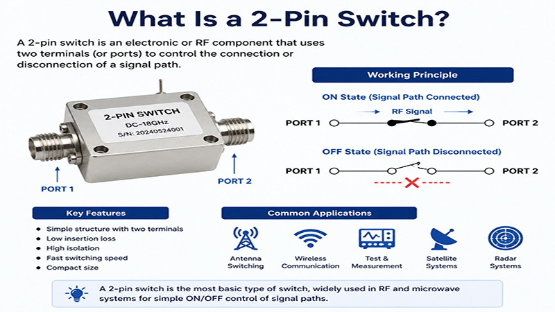
A PIN switch is one of the most widely used RF and microwave switching devices in modern communication systems. Built around the unique characteristics of the PIN diode, these switches provide high-speed switching, low insertion loss, excellent isolation, and long operational life. They are commonly found in radar systems, satellite communications, wireless infrastructure, test equipment, defense electronics, and 5G networks.
Unlike mechanical switches, PIN diode switches contain no moving parts, making them highly reliable for applications requiring millions or even billions of switching cycles. This article explains how a PIN switch works, its advantages, common configurations, applications, and key design considerations.
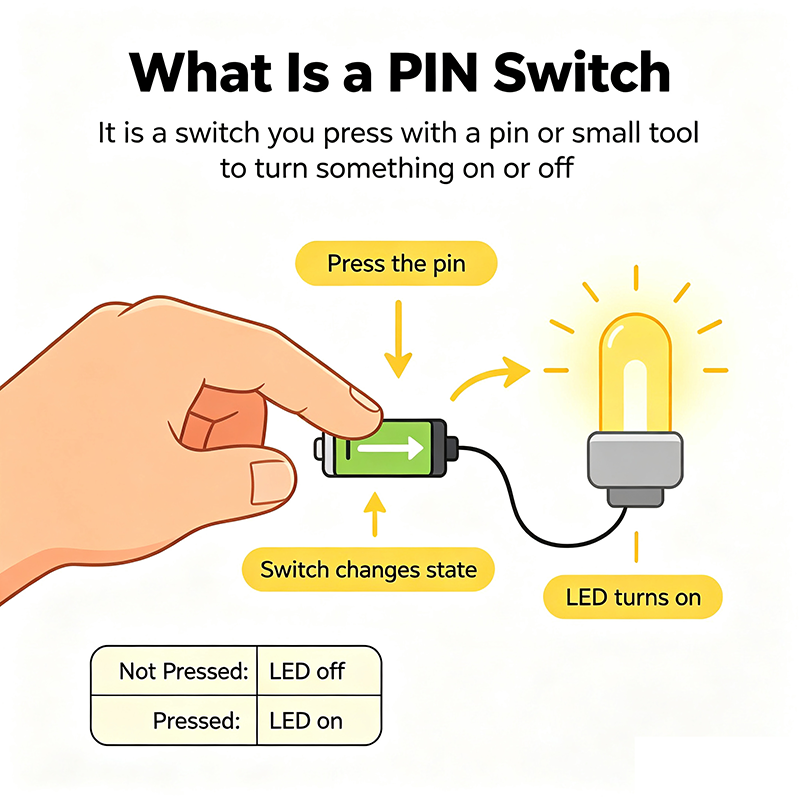
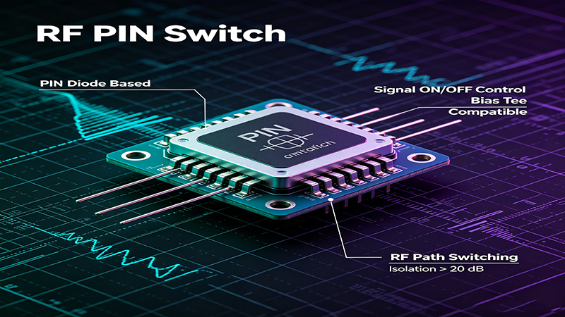
A PIN switch is an electronic RF switch that uses one or more PIN diodes to control the flow of radio frequency signals. A PIN diode contains three semiconductor layers:
The intrinsic layer significantly increases carrier lifetime, allowing the diode to behave as a variable RF resistor rather than a conventional rectifier at microwave frequencies.
By changing the DC bias current applied to the PIN diode, the RF impedance changes dramatically:
This simple principle enables fast, reliable RF switching across a broad frequency range.
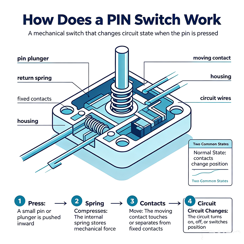
The operation of a PIN switch relies on controlling carrier concentration within the intrinsic region.
When forward current is applied, charge carriers fill the intrinsic layer, dramatically reducing RF resistance. The diode behaves like a low-value resistor, allowing RF energy to pass with minimal insertion loss.
Applying reverse voltage removes charge carriers from the intrinsic layer. The diode exhibits very high impedance, effectively blocking RF signal transmission and creating excellent isolation.
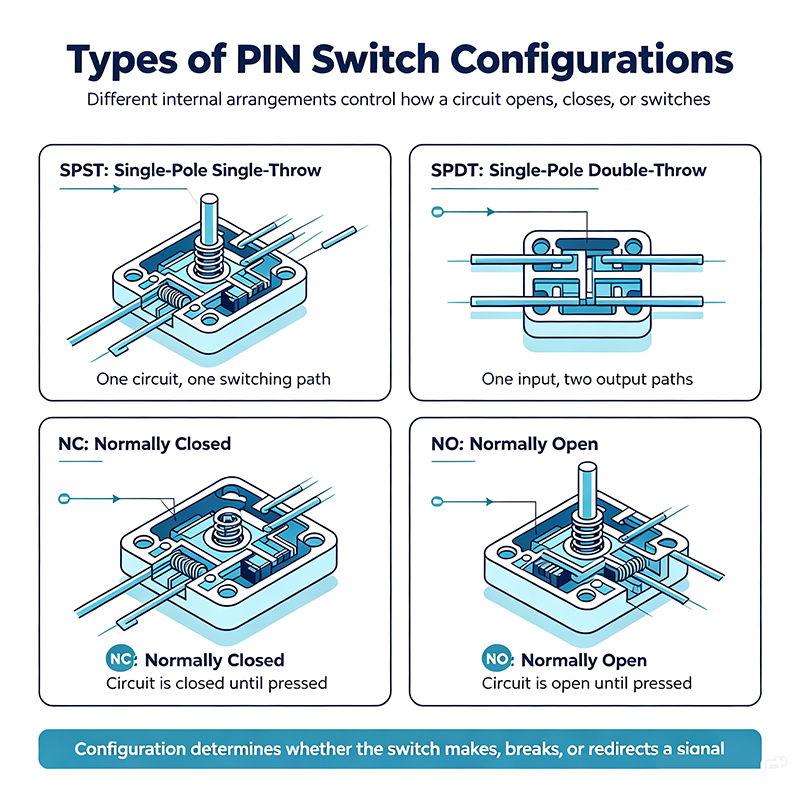
A series switch places the PIN diode directly in the RF signal path.
The diode is connected between the transmission line and ground.
Combining both series and shunt diodes provides superior isolation while maintaining low insertion loss.
PIN switches are available in various switching configurations:
| Parameter | Description |
|---|---|
| Frequency Range | Operating RF bandwidth |
| Insertion Loss | Signal attenuation in ON state |
| Isolation | Signal suppression in OFF state |
| Return Loss | Impedance matching performance |
| Switching Speed | Time required to change states |
| Power Handling | Maximum RF power capability |
| Control Voltage | Required DC bias voltage/current |
| Lifetime | Expected switching cycles |
PIN switches are essential components in numerous RF and microwave systems.
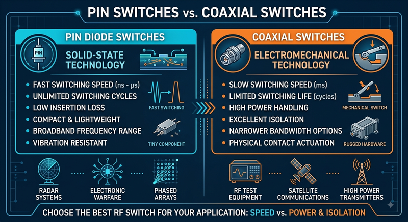
| Feature | PIN Switch | Mechanical RF Switch |
|---|---|---|
| Switching Speed | Nanoseconds to microseconds | Milliseconds |
| Lifetime | Extremely long | Limited mechanical cycles |
| Moving Parts | No | Yes |
| Power Consumption | Requires bias current | Minimal holding power |
| Reliability | Very high | Mechanical wear possible |
| Automation | Excellent | Moderate |
Designing an efficient PIN switch involves balancing RF performance with bias network stability. Engineers typically consider:
Careful PCB layout is especially important at microwave frequencies, where even small discontinuities can degrade insertion loss and return loss.
As wireless technologies continue advancing toward higher frequencies, PIN switch technology is evolving alongside them. Modern designs focus on:
Their intrinsic layer allows them to function as low-loss RF resistors, providing fast switching and excellent microwave performance.
Typical switching times range from several nanoseconds to a few microseconds, depending on circuit design and bias conditions.
Commercial PIN switches can operate from a few megahertz up to tens of gigahertz, with specialized designs exceeding 100 GHz.
Yes. A DC bias current or voltage is required to control the diode's operating state.
Yes. Properly designed PIN switches can handle high RF power levels and are commonly used in radar and military communication systems.
A PIN switch remains one of the most important technologies in RF and microwave engineering. Its combination of high switching speed, excellent reliability, low insertion loss, and broad frequency coverage makes it indispensable in modern communication, radar, aerospace, defense, and electronic testing applications.
Whether designing a high-frequency communication system or selecting components for RF instrumentation, understanding the operating principles and design considerations of PIN switches helps engineers achieve optimal signal integrity, efficiency, and long-term reliability.
High-tech Enterprise, Feifeng Talent
Chief Engineer Wang graduated with a master's degree in high-power microwave from the Institute of Electronics, University of Chinese Academy of Sciences.
View Full Profile