


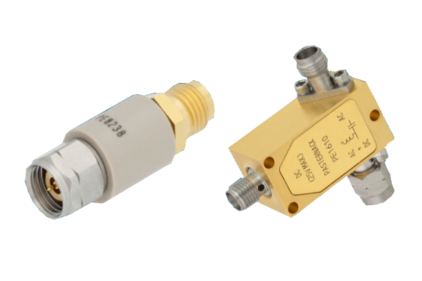
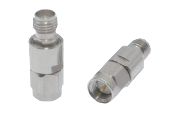
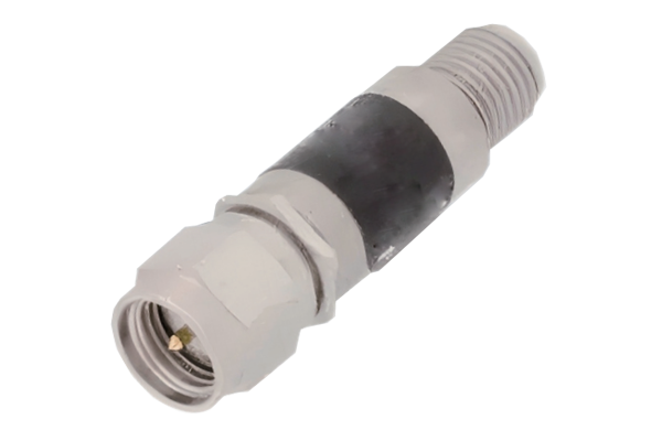
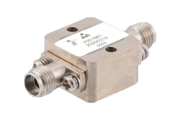




A digital phase shifter is an essential RF and microwave component that electronically controls the phase of a radio frequency signal. By introducing precise and programmable phase changes, it enables beam steering, signal synchronization, and advanced phase control in modern wireless communication and radar systems.
Digital phase shifters are widely used in phased array antennas, satellite communication, 5G infrastructure, electronic warfare, and microwave test equipment. Their ability to provide fast, repeatable, and electronically controlled phase adjustments makes them particularly valuable in systems requiring accurate beamforming without mechanical movement.
1. What Is a Digital Phase Shifter?
A digital phase shifter is an electronic device that changes the phase angle of an RF or microwave signal according to a digital control input. Unlike mechanical phase shifters, which rely on physical adjustments to modify signal propagation paths, digital phase shifters use semiconductor switches and carefully designed transmission-line or reactive networks.
The phase shift is typically expressed in degrees, such as 22.5°, 45°, 90°, or 180°. Depending on its resolution, a digital phase shifter can provide multiple discrete phase states across its operating frequency range.
For example, a 4-bit digital phase shifter offers 16 theoretically available phase states, while a 6-bit device provides 64 states. Higher resolution allows finer phase control and can improve beam-steering accuracy in phased array systems.
2. How Does a Digital Phase Shifter Work?
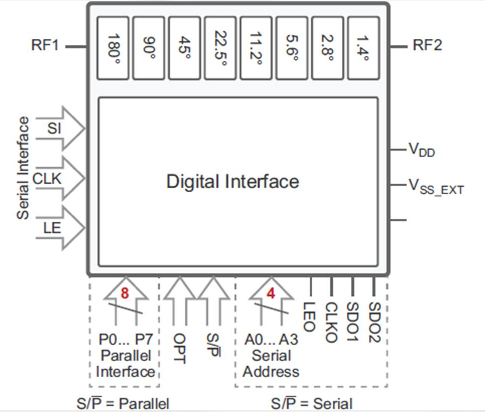
The working principle of a digital phase shifter is based on controlling the electrical length or reactive characteristics of an RF signal path. Digital control signals activate internal semiconductor switches, selecting different circuit configurations to produce specific phase delays.
2.1 Basic Operating Principle
A typical digital RF phase shifter consists of several functional blocks:
- RF Input: Receives the incoming RF or microwave signal.
- Phase-Shifting Network: Contains transmission lines, reactive elements, or switched networks that generate different phase delays.
- Control Circuit: Receives digital control bits from an external controller.
- RF Switching Elements: Select the required phase state using PIN diodes, FETs, or other semiconductor switches.
- RF Output: Delivers the phase-adjusted signal to the next stage of the system.
When the digital control word changes, the switching network selects a different signal path or impedance configuration. This changes the electrical phase of the output signal relative to the input.
2.2 Digital Phase Resolution
The phase resolution of a digital phase shifter depends on the number of control bits. For an ideal uniformly spaced phase shifter, the number of available states and phase increment are calculated as follows:
Phase Resolution = 360° / 2N
Where N represents the number of digital control bits.
| Digital Resolution | Number of States | Ideal Phase Resolution |
|---|---|---|
| 1-bit | 2 | 180° |
| 2-bit | 4 | 90° |
| 3-bit | 8 | 45° |
| 4-bit | 16 | 22.5° |
| 5-bit | 32 | 11.25° |
| 6-bit | 64 | 5.625° |
| 7-bit | 128 | 2.8125° |
| 8-bit | 256 | 1.40625° |
For example, a 6-bit digital phase shifter divides the full 360-degree phase range into 64 discrete states, with an ideal phase increment of 5.625 degrees.
Higher resolution provides finer phase adjustment, but it may also increase circuit complexity, control requirements, and implementation cost.
2.3 Phase Shift and Signal Behavior
A phase shifter ideally changes the phase of a sinusoidal signal without changing its amplitude or frequency.
A sinusoidal input can be represented as:
Where:
- A is the signal amplitude.
- f is the signal frequency.
- t is time.
- φ is the phase angle.
When a digital phase shifter introduces a phase change of Δφ, the output becomes:
In practical devices, Aout may differ slightly from the input amplitude because of insertion loss and phase-state-dependent amplitude variation.
3. Main Types of Digital Phase Shifters
Digital phase shifters can be categorized according to their circuit topology, switching technology, and phase-shifting mechanism. Different architectures offer different advantages in terms of bandwidth, insertion loss, phase accuracy, and power handling.
3.1 Switched-Line Phase Shifter
A switched-line phase shifter uses two or more transmission-line paths with different electrical lengths. Semiconductor switches select the required path to generate a specific phase difference.
The phase shift is determined by the difference in electrical length between the selected transmission lines.
- Relatively straightforward circuit architecture.
- Good phase accuracy with proper transmission-line design.
- Suitable for microwave and broadband applications when carefully optimized.
- Additional transmission-line length can increase circuit size.
- Switching discontinuities may affect impedance matching.
- Bandwidth and insertion loss depend on the implementation.
3.2 Loaded-Line Phase Shifter
A loaded-line phase shifter introduces controlled reactive elements into a transmission line. Switching different capacitive or inductive loading conditions changes the propagation characteristics and produces the desired phase shift.
This topology is often used when compact circuit dimensions and relatively simple phase-control structures are important.
Its performance depends heavily on the loading network, impedance matching, operating frequency, and bandwidth requirements.
3.3 Reflection-Type Phase Shifter
A reflection-type phase shifter generally uses a hybrid coupler and variable reflective loads. The input signal is divided into two paths, reflected by controlled loads, and recombined to produce a phase-adjusted output.
By switching the reactive loads, the circuit changes the reflection phase and therefore the output phase.
Reflection-type architectures can provide useful phase control in compact microwave implementations, although their insertion loss, bandwidth, and matching characteristics require careful optimization.
3.4 Vector-Modulator-Based Phase Shifter
A vector-modulator-based phase shifter controls the relative amplitudes of two orthogonal signal components, typically in-phase (I) and quadrature (Q) channels.
By adjusting the I and Q components, the circuit can generate different output phase angles. When digitally controlled, this architecture can provide programmable phase states with fine resolution.
Vector modulators are especially useful in advanced beamforming and broadband RF systems. However, amplitude accuracy, calibration, linearity, and control complexity are important design considerations.
4. Digital Phase Shifter vs. Analog Phase Shifter
Both digital and analog phase shifters are used to control RF signal phase, but they differ in their control methods and operating characteristics.
| Parameter | Digital Phase Shifter | Analog Phase Shifter |
|---|---|---|
| Control Method | Digital control signals | Analog voltage or current |
| Phase Adjustment | Discrete phase states | Typically continuous or quasi-continuous |
| Resolution | Determined by control bit depth | Determined by control range and circuit accuracy |
| Repeatability | Generally high for defined states | Can be affected by control accuracy and drift |
| Control Interface | Digital logic or serial interface | Analog bias or voltage control |
| System Integration | Well suited to digitally controlled beamforming | Useful in continuously adjustable RF systems |
| Applications | Radar, phased arrays, satellite systems | RF tuning, adaptive circuits, test systems |
The appropriate technology depends on whether the application prioritizes discrete repeatable phase states, continuous phase adjustment, control simplicity, or system-level integration.
5. Applications of Digital Phase Shifters in Phased Array Antennas
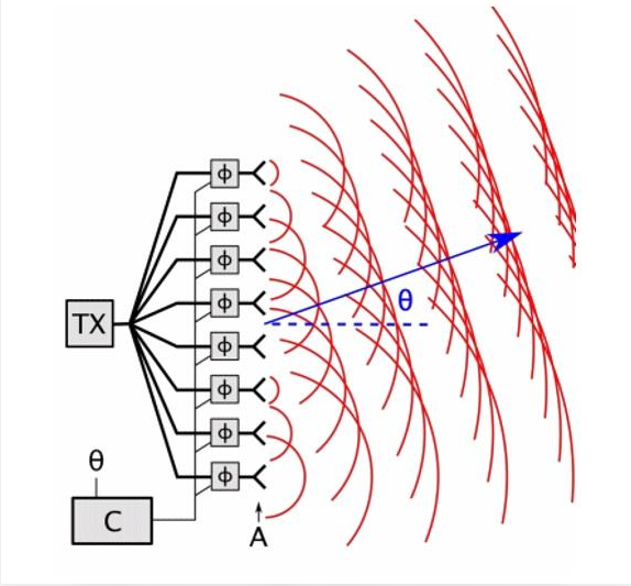
One of the most important applications of digital phase shifters is electronic beam steering in phased array antennas.
A phased array antenna consists of multiple radiating elements arranged in a specific geometric configuration. Each element receives or transmits an RF signal with a controlled phase relationship relative to the other elements.
By adjusting the phase of individual antenna elements, the system can change the direction of the combined radiation pattern without mechanically rotating the antenna.
5.1 Electronic Beam Steering
In a phased array antenna, the phase of each antenna element is carefully controlled to create constructive interference in the desired direction.
When the phase distribution across the array changes, the main radiation beam moves accordingly.
Digital phase shifters make this process programmable and repeatable, allowing radar and communication systems to rapidly change beam direction.
5.2 Phase Control in a Linear Antenna Array
For a uniformly spaced linear array, the progressive phase difference between adjacent elements determines the beam direction.
A simplified relationship is:
Where:
- Δφ is the progressive phase difference between adjacent antenna elements.
- d is the spacing between adjacent elements.
- λ is the operating wavelength.
- θ is the beam steering angle measured from broadside.
The sign depends on the adopted phase and coordinate convention.
For example, when the antenna elements are spaced at half a wavelength, a desired beam direction requires a corresponding phase progression across the array. Digital phase shifters implement this progression by assigning different phase states to individual RF channels.
5.3 Phased Array Radar Systems
Phased array radar systems use digital phase shifters to electronically scan the environment, track targets, and adjust radar beam direction.
Compared with mechanically steered radar antennas, electronically scanned arrays can provide faster beam repositioning and support multiple programmable scanning patterns.
Digital phase control is particularly important in modern defense radar, airborne radar, weather radar, and multifunction radar systems.
5.4 5G and 6G Wireless Communications
In 5G millimeter-wave communication systems, phased array antennas use beamforming to improve signal strength and compensate for high propagation losses.
Digital phase shifters allow base stations and user equipment to steer directional beams toward communication devices, helping improve link quality, coverage, and spectral efficiency.
Similar phase-control technologies are also relevant to emerging 6G research, including high-frequency communication, integrated sensing and communication, and advanced antenna architectures.
5.5 Satellite Communication Systems
Electronically steered phased array antennas are increasingly important in satellite communication terminals and ground stations.
Digital phase shifters enable antenna beams to track satellites electronically, reducing the need for bulky mechanical steering systems.
They are particularly useful in low Earth orbit (LEO) satellite communication terminals, where satellites move rapidly across the visible sky.
6. Key Performance Specifications of a Digital Phase Shifter
Selecting a digital phase shifter requires more than checking its nominal phase resolution. Several RF specifications determine its suitability for a particular application.
6.1 Operating Frequency Range
The operating frequency range defines the frequencies over which the device meets its specified RF performance.
Digital phase shifters are available for different frequency bands, including L-band, S-band, C-band, X-band, Ku-band, and Ka-band applications.
Always verify the specified phase accuracy, insertion loss, and return loss across the entire required frequency range rather than relying only on the nominal center frequency.
6.2 Phase Resolution and Phase Error
Phase resolution determines the smallest nominal phase increment between adjacent digital states.
Phase error measures the difference between the actual phase shift and the ideal phase shift for a given state.
Lower phase error is important in precision beamforming, radar tracking, and high-performance microwave systems.
6.3 Insertion Loss
Insertion loss represents the reduction in signal power as it passes through the phase shifter.
Excessive insertion loss can reduce the efficiency of an RF transmit or receive chain. In phased array systems, differences in insertion loss between channels can also cause amplitude imbalance across antenna elements.
6.4 Return Loss and VSWR
Return loss measures how effectively the phase shifter input and output are impedance matched to the connected RF system.
Good impedance matching reduces reflected power and helps maintain stable signal transmission.
6.5 Switching Speed
Switching speed describes how quickly the phase shifter can transition from one phase state to another while meeting specified performance requirements.
Fast switching is particularly valuable in electronically scanned radar, adaptive beamforming, and communication systems that frequently change beam direction.
6.6 Power Handling
Power handling defines the maximum RF power the device can withstand under specified operating conditions.
For high-power radar and transmitter applications, engineers should evaluate average power, peak power, input power limits, thermal characteristics, and switching conditions.
6.7 Amplitude and Phase Consistency
In multi-channel phased array systems, consistent performance across all RF channels is essential.
Amplitude imbalance and phase mismatch can distort the radiation pattern, increase sidelobe levels, and reduce beamforming accuracy.
| Specification | Why It Matters | Typical Evaluation Method |
|---|---|---|
| Frequency Range | Defines usable operating bandwidth | Frequency sweep |
| Phase Resolution | Determines phase adjustment granularity | Control-state measurement |
| Phase Error | Impacts beam pointing accuracy | Phase comparison |
| Insertion Loss | Affects RF link budget | VNA measurement |
| Return Loss | Indicates impedance matching | S11 measurement |
| Switching Speed | Determines phase transition time | Time-domain measurement |
| Power Handling | Determines maximum operating power | Power and thermal testing |
7. How to Choose the Right Digital Phase Shifter
Choosing the right digital phase shifter requires a detailed understanding of the system's RF requirements and operating environment.
7.1 Define the Operating Frequency
First, identify the required frequency band and bandwidth. The phase shifter should maintain acceptable phase accuracy and insertion loss throughout the intended operating range.
7.2 Determine the Required Phase Resolution
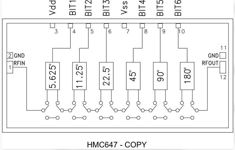
Choose the number of control bits according to the required beam-steering accuracy and system complexity.
- 3-bit: Suitable for applications where relatively coarse phase adjustment is acceptable.
- 4-bit: Provides 22.5-degree nominal phase steps.
- 5-bit: Provides finer phase control with 11.25-degree nominal steps.
- 6-bit or higher: Useful for applications requiring finer phase quantization.
7.3 Evaluate RF Loss and Matching
Compare insertion loss, return loss, VSWR, and amplitude variation across all phase states. These parameters directly influence the performance of the complete RF system.
7.4 Consider Control Compatibility
Check the digital interface, control voltage levels, logic compatibility, control timing, and switching behavior. The device should integrate smoothly with the FPGA, microcontroller, or beamforming controller used in the system.
7.5 Evaluate Environmental Requirements
For aerospace, defense, and outdoor communication applications, temperature range, vibration resistance, humidity tolerance, package reliability, and long-term stability may be important selection criteria.
8. Digital Phase Shifter vs. Digital Attenuator
Digital phase shifters and digital attenuators are both important components in modern RF systems, but they perform different functions.
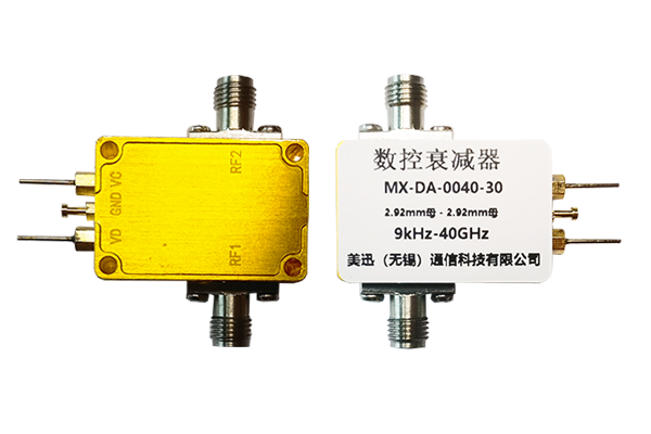
A digital phase shifter changes the phase angle of an RF signal, while a digital attenuator changes its amplitude or power level in discrete steps.
| Feature | Digital Phase Shifter | Digital Attenuator |
|---|---|---|
| Main Function | Controls signal phase | Controls signal amplitude |
| Control Unit | Degrees | Decibels (dB) |
| Primary Application | Beam steering and phase alignment | Power control and signal level adjustment |
| Typical System | Phased array antenna | RF receiver and transmitter |
| Common Control | Digital phase states | Digital attenuation steps |
In advanced phased array systems, digital phase shifters and digital attenuators may work together. Phase shifters control the relative phase of antenna channels, while attenuators adjust their amplitude to optimize the radiation pattern and sidelobe performance.
9. Challenges in Digital Phase Shifter Design
Although digital phase shifters provide flexible and repeatable phase control, several engineering challenges must be addressed.
9.1 Phase Quantization Error
Because digital phase shifters provide discrete rather than infinitely continuous phase states, the desired phase value may fall between two available settings. This creates quantization error, which can affect beam pointing accuracy and sidelobe levels.
9.2 Insertion Loss and Thermal Management
Internal semiconductor switches and passive RF networks introduce signal loss. In compact multi-channel arrays, accumulated losses can affect overall system efficiency and thermal performance.
9.3 Frequency-Dependent Phase Response
The phase shift produced by a circuit may vary with frequency. Maintaining consistent phase performance across a wide bandwidth requires careful electromagnetic simulation, circuit design, and manufacturing control.
9.4 Channel-to-Channel Calibration
Manufacturing tolerances and component variations can cause phase differences between nominally identical devices. Calibration and compensation techniques are often required to achieve accurate array-level beamforming.
10. Future Trends in Digital Phase Shifter Technology
As RF and microwave systems continue to evolve, digital phase shifter technology is developing toward higher frequencies, improved integration, lower power consumption, and more precise phase control.
- Millimeter-Wave Integration: Increasing demand for compact phase-control components in 5G and emerging 6G systems.
- Advanced Semiconductor Technologies: Improved RF SOI, CMOS, GaAs, and other semiconductor processes for enhanced integration and performance.
- Multi-Channel Beamforming: Greater integration of phase shifters with amplifiers, attenuators, and RF switching networks.
- Digital Calibration: More sophisticated calibration algorithms to compensate for phase and amplitude errors.
- Low-Power Architectures: Reduced control and operating power for portable and satellite communication terminals.
These developments are expected to support increasingly compact, efficient, and intelligent electronically steered antenna systems.
11. Frequently Asked Questions About Digital Phase Shifters
Q1: What is the main function of a digital phase shifter?
A digital phase shifter electronically changes the phase angle of an RF or microwave signal according to digital control inputs. Its primary functions include beam steering, phase alignment, and signal synchronization in RF systems.
Q2: How does a digital phase shifter work in a phased array antenna?
It adjusts the phase of individual antenna element signals. By establishing a controlled phase progression across the array, the system creates constructive interference in a desired direction and electronically steers the antenna beam.
Q3: What is the difference between a 4-bit and a 6-bit digital phase shifter?
A 4-bit phase shifter provides 16 discrete phase states with an ideal resolution of 22.5 degrees. A 6-bit phase shifter provides 64 states with an ideal resolution of 5.625 degrees, allowing finer phase control.
Q4: What frequency bands do digital phase shifters support?
Digital phase shifters are available for a wide range of RF and microwave frequencies, including L-band, S-band, C-band, X-band, Ku-band, and Ka-band. The actual supported frequency range depends on the device design.
Q5: Are digital phase shifters used in 5G systems?
Yes. Digital phase shifters are used in electronically steered antenna architectures and beamforming systems for 5G millimeter-wave communications. They help control antenna beam direction and improve directional signal transmission.
Q6: What is the difference between a phase shifter and an RF switch?
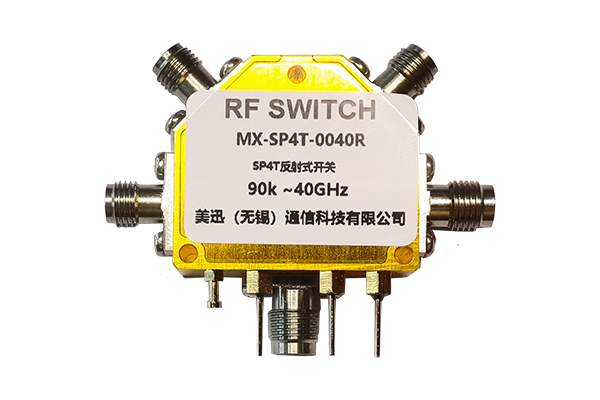
An RF switch selects or routes signals between different RF paths, while a phase shifter changes the phase relationship of a signal. Both components can be used together in advanced RF and microwave systems.
Q7: Why is phase resolution important in phased array antennas?
Phase resolution determines how accurately each antenna element can be assigned its desired phase. Higher resolution generally reduces phase quantization error and can improve beam-steering precision, although actual performance also depends on calibration, array geometry, and RF characteristics.
12. Conclusion
Digital phase shifters are fundamental components in modern RF and microwave engineering. By providing electronically controlled phase adjustment, they enable precise beam steering, signal synchronization, and flexible phase control in phased array antennas.
From 4-bit and 6-bit phase shifters to advanced multi-channel beamforming architectures, these devices support a wide range of applications in radar, satellite communication, 5G infrastructure, aerospace, and electronic warfare.
When selecting a digital phase shifter, engineers should carefully evaluate operating frequency, phase resolution, phase error, insertion loss, return loss, switching speed, power handling, and control compatibility.
As wireless communication and radar technologies advance toward higher frequencies and more integrated architectures, digital phase shifters will continue to play a critical role in next-generation RF and microwave systems.
Looking for Reliable RF and Microwave Components?
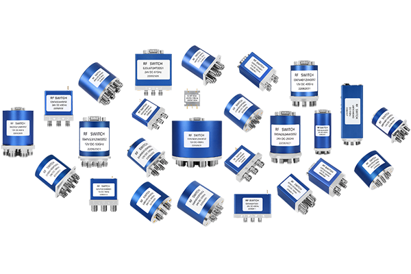
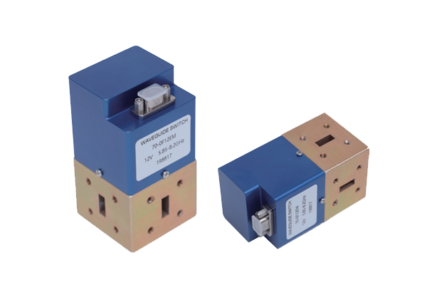
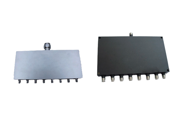
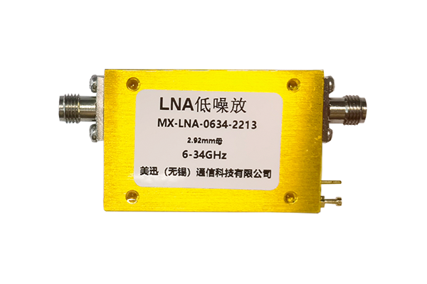
MeiXun specializes in RF and microwave components for demanding applications, including RF switches, coaxial switches, waveguide switches, power dividers, and low noise amplifiers.
Explore our RF and microwave solutions at MeiXun or contact our engineering team to discuss your application requirements.