






RF Power Detector Basics: RMS, Logarithmic, and Peak Detectors Explained
RF power detectors are essential components in wireless communication, radar systems, microwave test equipment, and automatic gain control circuits. They convert high-frequency signals into measurable electrical outputs, allowing engineers to monitor signal strength, regulate transmitter power, and protect sensitive RF components.
However, not all RF power detectors measure signals in the same way. RMS detectors estimate effective signal levels, logarithmic detectors provide a wide-range output proportional to power in decibels, and peak detectors capture signal amplitude peaks. Understanding these differences is critical when selecting an RF power detector for a specific application.
1. What Is an RF Power Detector?
An RF power detector is an electronic circuit or semiconductor device that converts an RF or microwave input signal into a lower-frequency voltage or current representing a characteristic of that signal. The output can then be processed by a microcontroller, analog-to-digital converter, feedback controller, or measurement instrument.
Depending on its architecture, a detector may respond to average power, RMS voltage, logarithmic signal level, envelope amplitude, or peak amplitude. The detector's output characteristic determines which measurements it can perform accurately.
How Does an RF Power Detector Work?
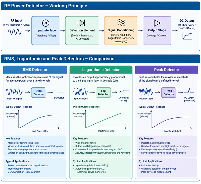
A typical RF detection system includes an input interface, a detection element, signal-conditioning circuitry, and an output stage. The RF signal is applied to the detector, which extracts the relevant signal characteristic and converts it into a usable baseband output.
- RF input: The detector receives a signal through a suitable RF interface.
- Signal detection: Diodes, transistors, or integrated detector circuits respond to the input waveform.
- Signal conditioning: Filtering, amplification, averaging, or logarithmic conversion shapes the output.
- Output measurement: The resulting voltage or current is measured or used for system control.
The exact process depends on the detector technology. For example, a diode-based detector may use rectification, while an integrated logarithmic detector may employ multiple detection stages and signal-processing circuitry.
2. RMS Power Detectors: Measuring Effective Signal Levels
An RMS power detector measures the root-mean-square value of a signal voltage or provides an output proportional to the signal's average power over a specified measurement interval. RMS detection is especially useful when signal amplitude varies over time or when the waveform is not a simple continuous sine wave.
What Does RMS Mean?
RMS stands for root mean square. For a voltage waveform, its value is calculated by squaring the instantaneous voltage, averaging the squared values over time, and taking the square root.
For a sinusoidal voltage, the RMS voltage equals the peak voltage divided by √2. For a known resistive load, average power can be calculated from RMS voltage using P = VRMS²/R. This relationship assumes that the voltage is measured across the relevant resistance and that the measurement conditions are appropriate.
How RMS Detection Works
A true-RMS detector implements or approximates the mathematical square-mean-square-root operation over its supported bandwidth and dynamic range. Some integrated devices perform this operation internally, while other measurement systems sample the waveform and calculate RMS digitally.
A true-RMS detector should not be confused with a simple envelope or average-responding detector calibrated for a sine wave. Non-sinusoidal signals can produce different readings when their crest factor or modulation characteristics change.
Advantages of RMS Power Detectors
- Provide meaningful measurements for many modulated and non-sinusoidal signals.
- Support average-power measurements when properly designed and calibrated.
- Help characterize signals with changing amplitude and complex modulation.
- Are useful in transmitter monitoring, communication testing, and RF power control.
Limitations of RMS Detectors
RMS detectors have finite bandwidth, response time, and dynamic range. Their performance can depend on waveform crest factor, input frequency, calibration, and measurement interval. They may also be more complex than basic envelope detectors.
An RMS reading does not automatically reveal the instantaneous maximum amplitude of a waveform. For applications with strict peak-power limits, a separate peak detector or an instrument capable of waveform capture may be required.
3. Logarithmic Detectors: Measuring RF Signals in Decibels
A logarithmic RF detector produces an output that changes approximately linearly with the input signal level expressed in decibels over a specified operating range. These detectors are widely used in receiver signal-strength measurement, automatic gain control, transmitter monitoring, and RF instrumentation.
How Does a Logarithmic Detector Work?
Many logarithmic detector ICs use cascaded gain and detection stages. As the RF signal propagates through the stages, the circuit combines their responses to create an output that approximates a logarithmic relationship with input amplitude or power.
The resulting output is commonly represented by a voltage that changes by a defined number of millivolts per decibel. The slope, intercept, frequency response, and linearity depend on the device and its calibration.
For power measurements referenced to 1 milliwatt, 0 dBm equals 1 mW, 10 dBm equals 10 mW, and 20 dBm equals 100 mW. A logarithmic detector can map a wide range of input levels into a convenient voltage range, simplifying subsequent processing.
Advantages of Logarithmic Detectors
- Offer a wide usable input range in many applications.
- Provide convenient voltage outputs representing signal levels in dB.
- Support compact receiver and transmitter power-monitoring designs.
- Can simplify automatic gain control and signal-strength indication.
Limitations of Logarithmic Detectors
Logarithmic detectors have finite accuracy, bandwidth, and dynamic range. Their response may vary with input frequency, temperature, waveform, and modulation. Near the lower detection limit or upper compression limit, the output may depart significantly from its ideal logarithmic relationship.
Engineers should also verify whether a device is specified as a logarithmic power detector or a logarithmic amplifier with an envelope detector. These terms are related but do not guarantee identical measurement behavior for every waveform.
4. Peak Detectors: Capturing Maximum Signal Amplitude
An RF peak detector identifies and holds, or otherwise reports, the maximum amplitude reached by a signal over a defined interval. It is useful when instantaneous peaks matter more than average signal level, such as in transmitter protection, pulse measurement, and monitoring signals with a high peak-to-average power ratio.
How Does a Peak Detector Work?
A conventional analog peak detector may use a rectifying element, a capacitor, and a buffer circuit. When the input envelope rises, the capacitor charges toward the detected peak. When the input falls, the capacitor retains the peak value until the circuit resets or the stored voltage decays.
Practical designs must balance acquisition speed, hold time, droop, reset behavior, and the ability to detect narrow pulses. Integrated RF peak detectors may use different circuit architectures to improve bandwidth and response.
Advantages of Peak Detectors
- Detect amplitude peaks that average-power measurements can conceal.
- Help monitor pulsed RF signals and high-crest-factor waveforms.
- Support overdrive detection and transmitter protection circuits.
- Can provide a simple analog indication of maximum envelope amplitude.
Limitations of Peak Detectors
A peak detector's reading depends on its response time, bandwidth, hold capacitor, discharge path, and reset interval. Very narrow peaks may be missed if the detector cannot respond quickly enough. Noise and spurious transients may also create false peak readings.
In addition, a peak voltage is not necessarily the same as peak RF power. Converting voltage to power requires the correct impedance assumptions and an understanding of whether the detector measures carrier amplitude, envelope amplitude, or another signal characteristic.
5. RMS vs. Logarithmic vs. Peak Detectors: Key Differences
The best RF detector depends on the parameter being measured, the signal waveform, the required response time, and the operating frequency range.
| Parameter | RMS Detector | Logarithmic Detector | Peak Detector |
|---|---|---|---|
| Primary measurement | RMS voltage or related average-power quantity | Signal level represented approximately in dB | Maximum detected amplitude |
| Typical output | Voltage or digital RMS value | Voltage proportional to input level in dB | Peak envelope voltage or peak indication |
| Modulated signals | Suitable when bandwidth and crest factor are within specifications | Useful for level monitoring; waveform dependence must be checked | Useful for tracking amplitude peaks within response limits |
| Dynamic range | Depends on detector architecture | Often wide, within specified limits | Depends on sensitivity, headroom, and circuit design |
| Response time | Depends on averaging and measurement bandwidth | Depends on detector bandwidth and filtering | Depends on attack time, pulse width, and hold circuit |
| Typical applications | Average-power measurement and modulated-signal analysis | RSSI, AGC, and RF level monitoring | Pulse monitoring, peak-envelope detection, and protection |
6. Common Applications of RF Power Detectors
Wireless Communication Systems
RF power detectors monitor transmit power, estimate received signal strength, and support automatic gain control. Logarithmic detectors are often useful for signal-level monitoring, while RMS-capable measurement circuits can be preferable when average power must be characterized for complex modulation.
Radar and Pulsed RF Systems
Radar transmitters and receivers may need to monitor short-duration pulses, peak envelope levels, and average power. Peak detectors can support fast amplitude monitoring, but pulse width, recovery time, and acquisition bandwidth must match the radar waveform.
RF Test and Measurement Equipment
Signal generators, power-monitoring modules, receiver test systems, and production test fixtures use RF detection to verify signal levels and support feedback loops. The choice of detector affects calibration, measurement uncertainty, and test throughput.
Automatic Gain Control and Transmitter Protection
In AGC systems, detector output is fed back to adjust gain and maintain a suitable signal level. In transmitter protection circuits, rapid detection can help identify excessive signal amplitude or abnormal operating conditions before they damage sensitive components.
Microwave and High-Frequency Systems
Microwave systems require careful attention to detector frequency response, input matching, connector transitions, and PCB layout. Parasitic capacitance, transmission-line discontinuities, and impedance mismatch can affect detector performance, particularly at higher frequencies.
7. How to Choose the Right RF Power Detector
Before selecting a detector IC or RF detection module, define the measurement objective and compare the device specifications against the actual operating conditions.
1. Determine the Required Measurement
Decide whether the system needs average power, RMS voltage, a dB-related signal-level output, envelope amplitude, or peak amplitude. Do not assume that a detector designed for one parameter can accurately measure another without waveform-specific calibration.
2. Check Frequency Range
Confirm that the detector covers the minimum and maximum input frequencies. Evaluate frequency-dependent sensitivity, gain variation, and calibration requirements across the entire operating band.
3. Evaluate Dynamic Range and Input Limits
The detector must resolve the weakest signal of interest without saturating at the strongest expected input. Check minimum detectable input, linear operating range, compression behavior, maximum safe input power, and any recommended external attenuation.
4. Match Response Time to the Signal
Continuous-wave signals, rapidly varying communication waveforms, and short RF pulses impose different response requirements. Compare detector rise time, fall time, video bandwidth, settling time, and pulse response where specified.
5. Verify Accuracy and Calibration
Review linearity, temperature drift, repeatability, frequency sensitivity, output noise, and calibration uncertainty. For accurate RF power measurement, account for impedance mismatch, cable loss, coupling loss, and the difference between detector output and actual power delivered to the load.
6. Consider Integration and Interface Requirements
Check supply voltage, current consumption, output range, interface compatibility, package, PCB footprint, and external component requirements. An integrated detector may reduce design complexity, while a discrete implementation may offer flexibility for specialized bandwidth or transient-response requirements.
8. Common RF Power Detector Design Mistakes
- Confusing average and peak power: A waveform with a high crest factor can have peaks far above its average level.
- Ignoring detector bandwidth: A detector may not accurately follow rapid envelope changes or short pulses.
- Assuming a fixed dB conversion: Logarithmic response slope and intercept can vary by device, frequency, and temperature.
- Overlooking impedance mismatch: Reflections at the RF interface can introduce power-measurement errors.
- Exceeding the input rating: Excessive RF power may cause compression, inaccurate readings, or permanent damage.
- Skipping calibration: Uncorrected cable loss, frequency response, and temperature effects can reduce measurement accuracy.
9. Frequently Asked Questions About RF Power Detectors
What is the main function of an RF power detector?
An RF power detector converts a characteristic of an RF signal, such as effective level, average-power-related level, logarithmic amplitude, or peak envelope amplitude, into a measurable output for monitoring, measurement, or feedback control.
What is the difference between an RMS detector and a peak detector?
An RMS detector evaluates the root-mean-square signal level over a measurement interval, whereas a peak detector captures the maximum detected amplitude. The two readings can differ substantially for pulsed or high-crest-factor signals.
Why are logarithmic RF detectors commonly used in wireless systems?
Logarithmic detectors provide an output related to input signal level in decibels. This makes them convenient for received-signal strength indication, transmitter monitoring, and automatic gain control over a wide specified input range.
Can a logarithmic detector measure RF power directly?
It can estimate power when the detector is specified and calibrated for that purpose under the relevant frequency, waveform, and impedance conditions. Some devices respond primarily to RF amplitude rather than true average power, so the datasheet and calibration method must be checked.
Which RF detector is best for modulated signals?
An RMS detector is often appropriate when average power of a complex modulated signal is required. A logarithmic detector may be better for convenient signal-level monitoring, while a peak detector is useful when envelope peaks are important. The final choice depends on modulation bandwidth, crest factor, required accuracy, and detector specifications.
What specifications matter most when selecting an RF detector?
Key specifications include operating frequency, input power range, dynamic range, sensitivity, linearity, response time, video bandwidth, temperature stability, output interface, and calibration accuracy. Maximum input power and waveform compatibility are also important.
Conclusion
RMS, logarithmic, and peak detectors serve different purposes in RF and microwave systems. RMS detectors are valuable for effective signal-level and average-power measurements. Logarithmic detectors simplify dB-related signal monitoring and gain-control applications. Peak detectors help identify maximum envelope amplitude and fast transients.
The best solution depends on the required measurement, RF frequency, input power range, waveform characteristics, response time, and accuracy target. By evaluating these factors early in the design process, engineers can select a detector that improves system reliability and measurement confidence.
Explore RF and Microwave Components for Your Next Design
Reliable RF measurement begins with selecting components that match your frequency range, signal level, and system performance requirements. Explore RF and microwave solutions from MeiXun for communication, test and measurement, and other high-frequency applications.
Explore MeiXun RF ComponentsAbout the Author — MeiXun Team
Chief Engineer Wang
High-tech Enterprise, Feifeng Talent
Chief Engineer Wang graduated with a master's degree in high-power microwave from the Institute of Electronics, University of Chinese Academy of Sciences.
View Full Profile- RF Switch Circuit Diagram
- RF Switch
- Ohm's Law
- dBm to Watt
- mW to dBm
- Wavelength to Frequency
- RF Connector
- SMA Connector
- RF Switch Module
- RF Coupler
- RF PIN Switch
- Microwave Coaxial Switch
- PIN Switch
- Coaxial RF Switch
- Waveguide Switch
- Microwave Switch
- Low Noise Amplifier
- PIN Diode Switch
- Coaxial Switch
- RF Microwave Switch
- SPST Switch