RF Switch Life Cycle: Understanding Operating Cycles and Reliability
Every RF switch has a finite life cycle. Whether it is a coaxial electromechanical relay, a PIN-diode solid-state switch, or an MEMS device, understanding operating cycles and reliability metrics is essential for designing test systems, radar front-ends, and wireless infrastructure that perform reliably for years.
Quick Answer
An RF switch life cycle is the number of operating cycles — defined as one complete switch actuation from one state to another and back — that a switch can perform before its electrical or mechanical performance degrades beyond specification. Manufacturers typically quote life in cycles (e.g., 1 million, 10 million, 100 million) and reliability in MTBF hours. Extending life requires derating power, minimizing hot switching, controlling temperature, and following the manufacturer's specified load limits.
What Is an "Operating Cycle"?
For most RF switches, one operating cycle = one transition between two states. For example:
A SPDT coaxial switch counts a cycle every time the contact moves from port A to port B (or vice versa).
A PIN-diode switch counts a cycle when the bias state changes (on/off or forward/reverse).
A transfer switch counts a cycle when the routing configuration changes.
Some manufacturers also report a "hot-switching" cycle, in which RF power is present during the transition. Hot-switching is far more stressful than "cold-switching" (switching with no RF signal) and dramatically reduces life.
Mechanical vs. Solid-State vs. MEMS Switch Life
Mechanical
Electromechanical RF Switch
Coaxial relays with moving metal contacts. Typical life: 1M – 10M cycles. Excellent RF performance, low insertion loss, but limited by contact wear and arcing.
Solid-State
Solid-State PIN Switch
PIN diodes or FETs route RF with no moving parts. Typical life: 100M – 1B cycles. Fast switching, but higher insertion loss and limited power handling.
MEMS
RF MEMS Switch
Micro-electromechanical beams that physically deflect. Typical life: 1B – 100B cycles. Excellent linearity, low loss, but sensitive to humidity and stiction.
Hybrid
Latching Relay
Magnetic latching relays hold position without continuous current. Typical life: 5M – 20M cycles. Very low quiescent power, suited for battery-driven systems.
The single biggest factor. Hot switching (transitioning while RF power is applied) causes arcing, contact welding, and diode burnout. Cold switching (RF off during transition) can extend life by 10× – 100×.
2. Contact Wear and Arcing
In electromechanical switches, every actuation creates a small arc that erodes the gold or silver-plated contacts. Over millions of cycles, contact resistance rises and insertion loss drifts upward.
3. Power Level
Higher RF power = larger arc energy per cycle. Most coaxial switches are rated for "cold-switched" power up to several hundred watts; "hot-switched" power is typically limited to 1 – 10 W.
4. Switching Speed and Bounce
Slow switching with contact bounce causes multiple micro-arcs per actuation. Faster, crisper switching limits damage.
5. Temperature
Heat accelerates contact oxidation, polymer degradation, and MEMS stiction. Each 10 °C rise roughly halves the life of many components (Arrhenius law).
6. Frequency
At higher frequencies, skin effect concentrates current at the contact surface, accelerating wear. Some switches are rated for fewer cycles at higher frequencies.
7. Load Mismatch (VSWR)
A mismatched load reflects power back into the switch, multiplying voltage and current stress on the contacts.
Reliability Metrics
Metric
Meaning
Cycles to Failure
Mean number of actuations before spec violations
MTBF
Mean Time Between Failures (hours)
MTTF
Mean Time To Failure (non-repairable)
Failure Rate (λ)
Failures per million hours (FIT = failures per 10⁹ hours)
Service Life
Calendar years before end-of-life
B10 Life
Time at which 10 % of units have failed
Visualizing Life vs. Switching Rate
Operating Cycles vs. Time at Different Switching Rates
Total cycles a switch performs over a 5-year service window, depending on how often it is actuated.
Bars show cumulative cycles over a 5-year window. A switch rated for 10 million cycles is suitable only at the lowest switching rate; MEMS and solid-state parts handle high-rate switching far better.
How Manufacturers Test Life
Manufacturers do not run switches to actual failure; instead they use accelerated life testing (ALT) and highly accelerated life testing (HALT):
Run switches at elevated temperature, voltage, and cycling rates.
Extrapolate results to normal operating conditions using Arrhenius or Coffin-Manson models.
Publish conservative life ratings that include safety margins (typically 50 – 80 %).
Pro Tip: A datasheet life rating of "5 million cycles" typically means 5 million cycles under specified conditions. Operating at higher power, higher VSWR, or higher temperature can cut that life by 5× – 10× without warning. Always read the "conditions" footnote.
How to Extend RF Switch Life
1. Cold Switch Whenever Possible
Turn off RF before transitioning. Cold switching extends life by 10× – 100× and is the single most effective way to improve reliability.
2. Derate Power by 50 %
Run at half the rated hot-switched power. Arc energy scales with voltage and current, so even small reductions help significantly.
3. Control Temperature
Use heatsinks, fans, or thermal management. Each 10 °C drop in junction or contact temperature approximately doubles life.
4. Match Loads Properly
Use terminations with VSWR < 1.5:1. High reflected power multiplies voltage stress on the contacts.
5. Use Latching Relays
For systems that hold a state for long periods, magnetic latching relays consume no current when idle — ideal for low-power or remote sites.
6. Add a Redundant Path
Critical systems should include a bypass or spare switch that takes over if the primary fails. Failure isolation prevents whole-system outages.
7. Cycle Slowly on Purpose
Avoid unnecessary switching. If a port is connected for a long measurement, hold the position rather than toggling.
8. Monitor Contact Resistance
Track insertion loss or contact resistance over time. A slow upward drift is the first sign of contact wear and can trigger scheduled replacement before failure.
Lab ATE typically switches a few times per second. A 10M-cycle coaxial switch lasts many years under these conditions. Cold-switching and derated power extend that further.
Radar & Phased Arrays
T/R modules switch every pulse — billions of cycles per day. Solid-state PIN-diode or FET switches are mandatory; mechanical switches are unsuitable.
Wireless Infrastructure
Base-station antenna switches cycle relatively slowly but must operate outdoors for 10+ years. Solid-state or latching relays dominate, with redundancy for hot-swap.
Satellite & Space
Space-grade switches must operate for 15+ years with no maintenance. Only solid-state or specially qualified latching relays are used, with extreme derating.
Medical & Industrial Imaging
MRI and ultrasound switches cycle rapidly but at low power. Solid-state PIN or FET switches are the standard.
Key Takeaways
RF switch life cycle is measured in operating cycles and reliability hours.
Hot switching is the dominant life-reducing factor; cold switching can extend life 10× – 100×.
Mechanical switches give the lowest insertion loss; solid-state and MEMS switches give the longest life.
Manufacturers rate life using accelerated testing under specified conditions.
Derating power, controlling temperature, matching loads, and using redundancy all extend field life significantly.
Frequently Asked Questions
What is an operating cycle for an RF switch?
One operating cycle is one complete actuation between two switch states. For a SPDT switch, moving from port A to port B (and optionally back) counts as one cycle.
How long do RF switches last?
Mechanical coaxial switches typically last 1 – 10 million cycles. Solid-state switches reach 100 million to 1 billion cycles. RF MEMS devices can exceed 1 billion cycles.
What is hot switching?
Hot switching is changing the RF path while RF power is present. It causes arcing and dramatically shortens life. Cold switching — turning off RF before transitioning — can extend life by 10× – 100×.
How is RF switch reliability measured?
Manufacturers use accelerated life testing at elevated temperature, voltage, and cycling rates, then extrapolate results using physics-of-failure models. Published life ratings include safety margins of 50 – 80 %.
Can I replace a mechanical switch with a solid-state one to extend life?
Often yes, but with trade-offs: solid-state switches have higher insertion loss, lower power handling, and limited isolation at high frequencies. Always verify the RF specs meet your system requirements before substituting.
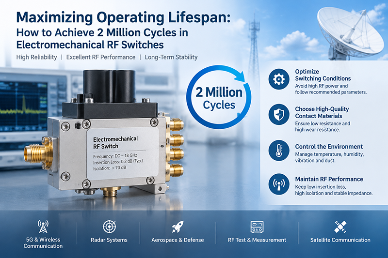
Electromechanical RF switches are widely used in advanced communication systems, aerospace electronics, automated test equipment, radar systems, and wireless infrastructure due to their excellent RF performance, high isolation, and low insertion loss.
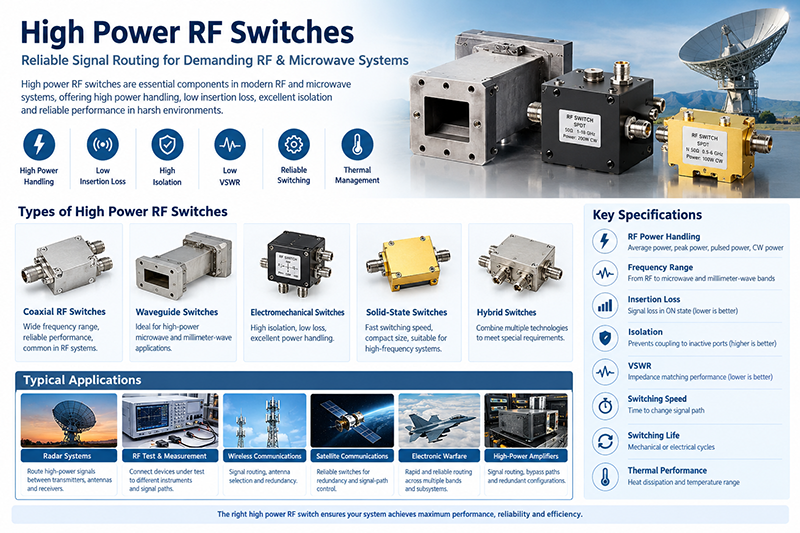
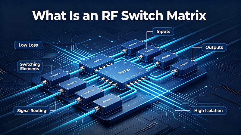
High power RF switches are essential components in modern RF and microwave systems where signal routing must be performed while handling substantial radio-frequency power.
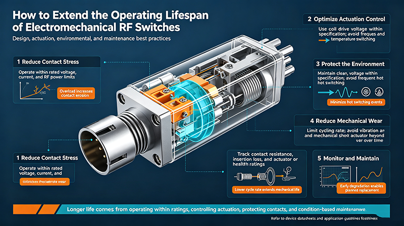
How to extend the operating lifespan of electromechanical RF switches. Practical guidance on cold switching, derating, contact wear, environment, and maintenance for coaxial and waveguide RF switches.
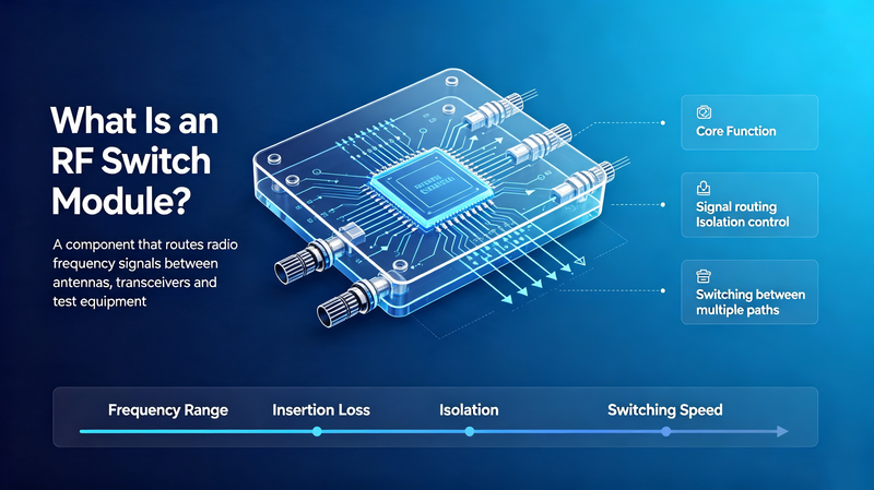
An RF Switch Module is a critical microwave component used to control the routing of radio frequency signals between multiple circuits, antennas, or test channels.
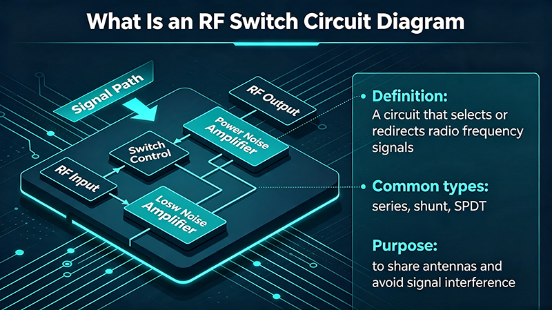
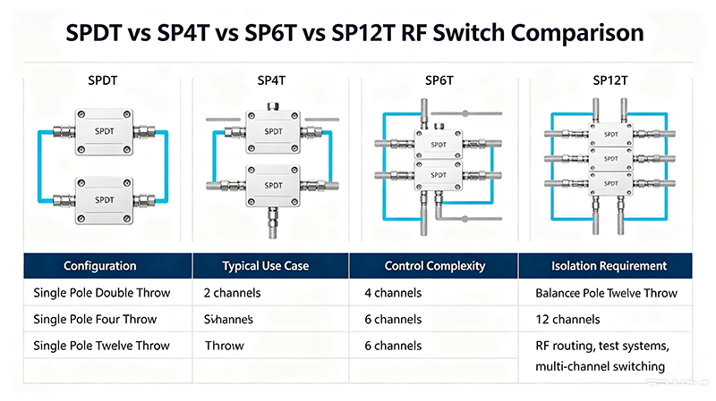
RF switches are essential components in modern wireless communication, radar systems, test equipment, and satellite applications. Among the most commonly used configurations are SPDT, SP4T, SP6T, and SP12T RF switches.
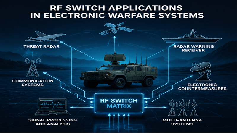
Electronic warfare (EW) systems require extremely fast, reliable, and precise control of radio frequency signals. RF switches play a critical role in modern electronic warfare architectures by enabling rapid signal routing, antenna selection, frequency management, and protection of sensitive RF components.
Aug 04 ,26
About the Author — MeiXun Team
Wang
Chief Engineer Wang
High-tech Enterprise, Feifeng Talent
Chief Engineer Wang graduated with a master's degree in high-power microwave from the Institute of Electronics, University of Chinese Academy of Sciences.
View Full Profile
Wang
Chief Engineer Wang
High-tech Enterprise, Feifeng Talent
Chief Engineer Wang graduated with a master's degree in high-power microwave from the Institute of Electronics, University of Chinese Academy of Sciences.
In the same year, he joined CETC 40/41 for work and study. He has been committed to the design and development of microwave switches for a long time.
He has applied for 27 patents as the first inventor in the microwave switch field, with 6 authorized invention patents and 14 utility model patents.
The products he developed cover various application platforms such as civilian testing, vehicle-mounted, shipborne, airborne, and missile-borne.