

























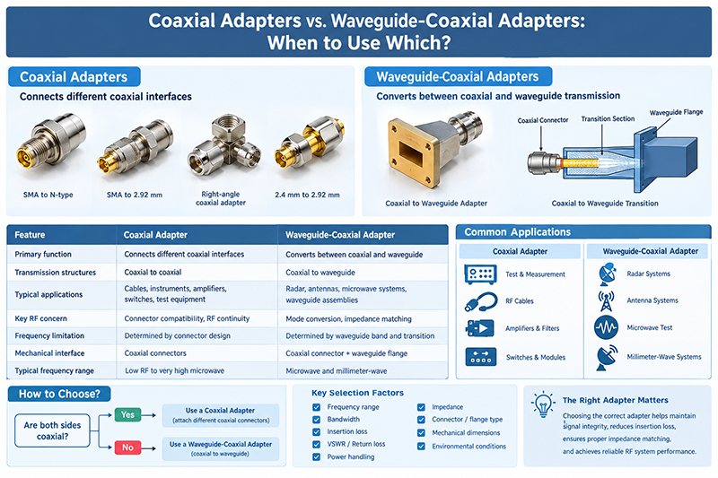
Coaxial adapters and waveguide-coaxial adapters are both used to connect RF and microwave components, but they solve different interconnection problems.
Sep 22 ,26


5G communication testing, wireless terminal automated testing
Aerospace communication systems
Precision measurement equipment, radio frequency signal control of radar transmitters
Communication and navigation systems
Optical communication module-related testing
Interconnection of wireless communication base stations
A waveguide is a transmission structure designed to guide electromagnetic waves from one location to another. Waveguides are widely used in RF and microwave systems because they can transmit high-frequency signals with low loss and high power-handling capability.
Unlike conventional coaxial cables, which carry electromagnetic energy through a conductor and dielectric structure, a waveguide typically uses a hollow metallic structure to confine and direct electromagnetic energy. This makes waveguides particularly useful at microwave and millimeter-wave frequencies where conventional transmission lines can experience increasing losses.
Waveguide definition: A waveguide is a physical structure that confines and guides electromagnetic waves between two points, most commonly at microwave and millimeter-wave frequencies.
Waveguides are essential components in many modern communication, radar, satellite, aerospace, defense, and test-and-measurement systems. Common waveguide components include waveguide switches, waveguide filters, waveguide couplers, waveguide antennas, waveguide transitions, and waveguide power dividers.
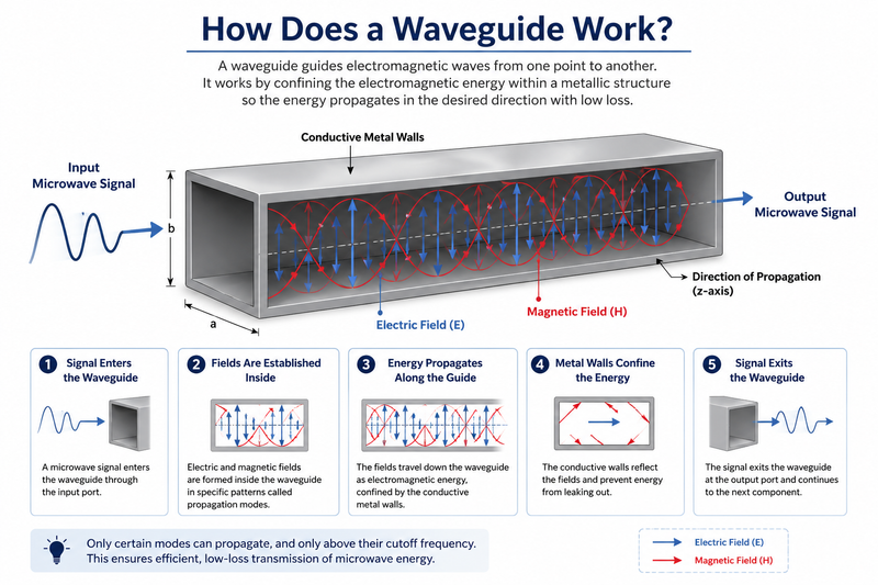
A waveguide works by confining electromagnetic energy within its physical boundaries and allowing the energy to propagate along a defined path. In a conventional rectangular waveguide, the inner metallic walls reflect electromagnetic waves and prevent the energy from escaping through the sides.
The electromagnetic field inside the waveguide forms specific field patterns called modes. Each mode has a particular electric-field and magnetic-field distribution and can propagate only when the operating frequency is above its corresponding cutoff frequency.
The most common mode in a rectangular waveguide is the TE10 mode. TE stands for transverse electric, meaning that the electric field has no component in the direction of propagation.
The electric and magnetic fields interact within the waveguide and transport electromagnetic energy along its length.
The conductive walls confine the electromagnetic energy and provide the reflection mechanism needed for wave propagation.
Only specific electromagnetic modes can propagate inside a waveguide, depending on its dimensions and operating frequency.
A waveguide has a minimum frequency below which a particular mode cannot propagate effectively.
Cutoff frequency is one of the most important characteristics of a waveguide. It represents the minimum frequency at which a particular electromagnetic mode can propagate through the waveguide.
For a rectangular waveguide, the cutoff frequency for a specific mode can be expressed as:
Here, fc is the cutoff frequency, c is the speed of light in free space, a and b are the internal dimensions of the rectangular waveguide, and m and n represent the mode indices.
For reliable operation, the operating frequency is normally selected above the cutoff frequency of the desired propagation mode while remaining below the cutoff frequency of higher-order modes.
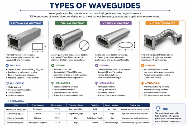
Waveguides are available in several physical configurations. The appropriate type depends on frequency, power level, mechanical requirements, and system architecture.
The rectangular waveguide is one of the most widely used waveguide types. It has a rectangular cross-section and is commonly manufactured from conductive materials such as aluminum, copper, or plated metal.
Rectangular waveguides support several propagation modes, with TE10 generally being the dominant mode. They are widely used in radar, microwave communication, satellite systems, antennas, and RF test equipment.
A circular waveguide has a cylindrical cross-section. Circular waveguides can support different TE and TM modes and are useful in applications requiring rotational symmetry or specific polarization characteristics.
They can be found in radar systems, antenna feeds, microwave communication equipment, and specialized RF systems.
An elliptical waveguide has an elliptical cross-section and can offer mechanical flexibility and useful transmission characteristics in certain microwave applications. Flexible waveguide structures are often used where installation routing is difficult.
Flexible waveguides are designed to accommodate mechanical movement or alignment requirements. They are particularly useful for connecting rigid waveguide sections to antennas or other components when precise mechanical positioning is required.
The electromagnetic field inside a rectangular waveguide can exist in different propagation modes. These modes are commonly identified using TEmn and TMmn notation.
Waveguide dimensions are carefully selected to establish a suitable operating frequency range and minimize the risk of unwanted higher-order mode propagation.

Waveguides and coaxial cables are both used to transmit RF and microwave signals, but they have significantly different electrical and mechanical characteristics.
| Feature | Waveguide | Coaxial Cable |
|---|---|---|
| Typical Frequency | Microwave and millimeter-wave | From low RF to microwave frequencies |
| Transmission Loss | Generally low at high microwave frequencies | Depends strongly on cable construction and frequency |
| Power Handling | High | Low to high depending on cable type |
| Operating Mode | TE and TM modes | TEM mode in conventional coaxial transmission |
| Mechanical Size | Can become large at lower frequencies | Generally more compact |
| Flexibility | Usually rigid, with flexible options available | Highly flexible |
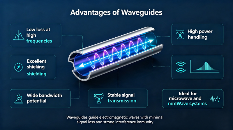
Waveguides offer several advantages for high-frequency RF and microwave applications.
At microwave frequencies, waveguides can provide very low transmission loss compared with many conventional transmission-line technologies. This is especially important in systems where signal power and link efficiency are critical.
Waveguides can handle high RF power levels because the electromagnetic field is distributed within the waveguide structure rather than concentrated in a small dielectric region.
Waveguides are well suited to microwave and millimeter-wave frequencies. They are commonly used in applications where conventional cables become increasingly lossy or difficult to implement efficiently.
Properly designed waveguide systems can provide excellent electromagnetic shielding and isolation, making them useful in demanding RF systems such as radar and electronic warfare equipment.
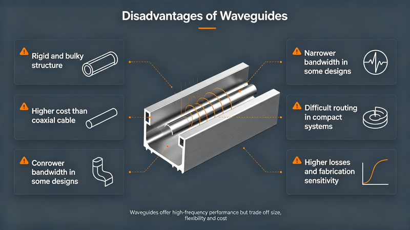
Despite their excellent microwave performance, waveguides also have several limitations.
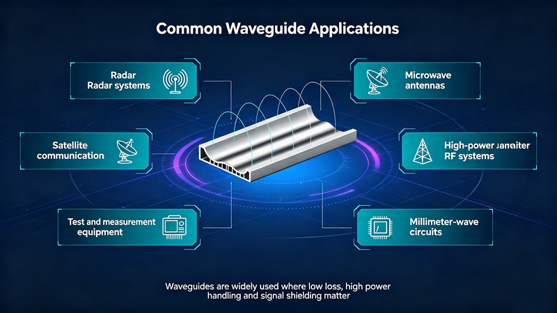
Waveguides are used across many high-frequency technologies where low loss, high power handling, and controlled electromagnetic propagation are important.
Waveguides are widely used in radar transmitters, receivers, antenna feeds, duplexers, filters, and microwave switching networks.
Satellite communication systems use waveguide components to efficiently route microwave and millimeter-wave signals.
High-frequency communication systems use waveguide assemblies and components for reliable signal transmission.
Waveguide components are used in high-frequency RF architectures requiring high isolation, power handling, and low insertion loss.
Waveguide interfaces and components are frequently used in microwave test systems, network analyzers, and high-frequency measurement equipment.
Waveguides are commonly used as antenna feeds and can also form part of horn and other microwave antenna structures.
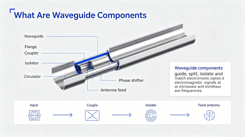
A complete waveguide system normally consists of more than a simple transmission section. Different waveguide components are used to control, route, filter, divide, combine, or switch microwave signals.
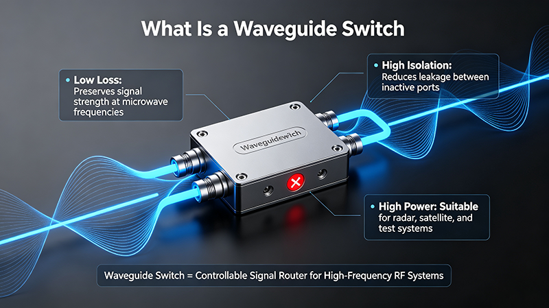
Waveguide switches are used to route microwave signals between different transmission paths. They are commonly used in radar, satellite communication, automated test systems, and RF switching networks.
Waveguide filters selectively pass or reject specific frequency ranges. They are used to control unwanted signals and establish the required frequency response of microwave systems.
Waveguide couplers transfer a controlled amount of electromagnetic energy between transmission paths. They are useful for signal monitoring, measurement, power sampling, and RF distribution.
Waveguide power dividers split microwave power into multiple output paths. Depending on the design, they can provide specific amplitude and phase relationships between the output ports.
A waveguide-to-coaxial transition connects a waveguide system to a coaxial RF system. These transitions are important when integrating different transmission technologies within the same RF architecture.
When selecting a waveguide or waveguide component, engineers should evaluate several important specifications.
Choosing the correct waveguide requires balancing electrical performance, mechanical constraints, and application requirements.
Start by identifying the minimum and maximum operating frequencies. The selected waveguide size should support the desired frequency band while maintaining appropriate mode operation.
Determine the maximum RF power that the waveguide will carry. High-power radar and transmitter applications may require waveguide structures specifically designed for high-power operation.
For sensitive microwave systems, low insertion loss and low VSWR can significantly improve overall system performance.
Check the required flange configuration, mechanical dimensions, connector transitions, and mounting requirements before selecting the waveguide.
For aerospace, defense, outdoor, and industrial applications, environmental requirements can be just as important as electrical specifications.
Engineering tip: Do not select a waveguide based only on its nominal frequency range. Mode behavior, VSWR, insertion loss, power handling, flange compatibility, environmental conditions, and mechanical tolerances should all be considered.
As operating frequencies increase, transmission-line losses and power-handling limitations become increasingly important. Waveguides provide an efficient method of transporting electromagnetic energy at microwave and millimeter-wave frequencies.
Their ability to provide low loss, high power handling, excellent isolation, and predictable electromagnetic behavior makes them particularly valuable in advanced RF systems.
Modern applications such as 5G infrastructure, satellite communications, radar, aerospace electronics, electronic warfare, microwave instrumentation, and millimeter-wave research continue to rely on waveguide technology.
A waveguide is a structure that guides electromagnetic waves from one point to another. It is commonly used for microwave and millimeter-wave signals.
The main purpose of a waveguide is to efficiently transmit electromagnetic energy while controlling its propagation characteristics.
Waveguides can provide low transmission loss and high power handling at microwave frequencies, making them suitable for applications where conventional transmission lines may become less efficient.
The TE10 mode is the dominant mode of a standard rectangular waveguide. It has the lowest cutoff frequency among the supported modes of that structure.
A coaxial cable normally supports a TEM transmission mode using a center conductor and outer conductor, while a hollow metallic waveguide supports TE and TM modes. Waveguides are particularly advantageous for many high-frequency and high-power microwave applications.
Common applications include radar systems, satellite communications, microwave communication, electronic warfare, RF testing, antenna systems, and millimeter-wave equipment.
A waveguide is a fundamental RF and microwave transmission structure designed to guide electromagnetic energy efficiently from one point to another. By controlling electromagnetic field propagation through its physical dimensions, a waveguide can provide low loss, high power handling, and excellent performance at microwave and millimeter-wave frequencies.
Understanding waveguide types, propagation modes, cutoff frequency, VSWR, insertion loss, and power handling is essential when designing or selecting microwave components. From radar and satellite communication to electronic warfare, RF testing, and advanced wireless systems, waveguide technology remains an important part of modern high-frequency engineering.
For demanding microwave applications, selecting the appropriate waveguide and compatible components such as waveguide switches, filters, couplers, transitions, and power dividers can significantly improve overall RF system performance and reliability.



High-tech Enterprise, Feifeng Talent
Chief Engineer Wang graduated with a master's degree in high-power microwave from the Institute of Electronics, University of Chinese Academy of Sciences.
View Full Profile