


























Complete guide to RF coaxial connectors: SMA, BNC, N-type, TNC and more. Compare types, frequencies, impedance and applications with our selection chart.
Sep 15 ,26


5G communication testing, wireless terminal automated testing
Aerospace communication systems
Precision measurement equipment, radio frequency signal control of radar transmitters
Communication and navigation systems
Optical communication module-related testing
Interconnection of wireless communication base stations
A comprehensive breakdown of RF coaxial connector types, their specifications, frequency ranges, and real-world applications for engineers and technicians.
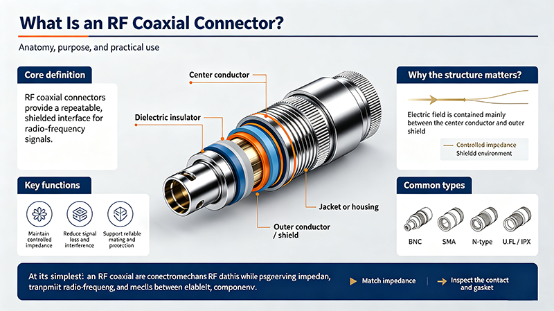
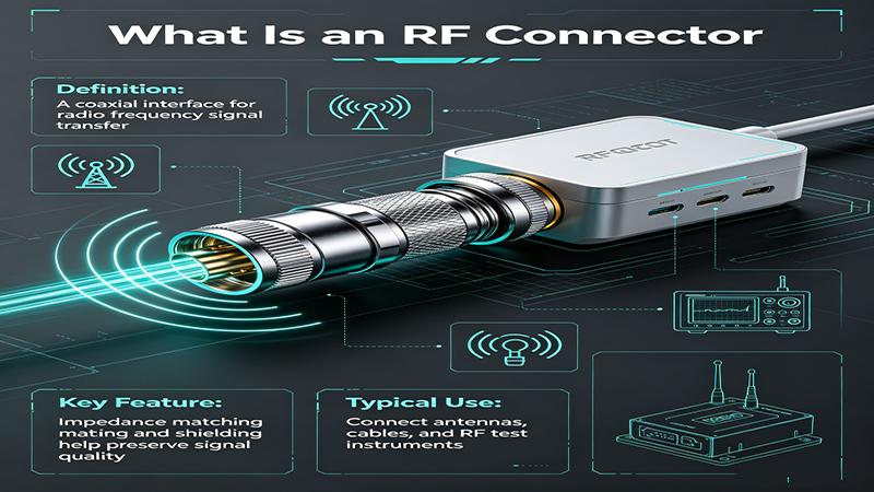
Radio frequency (RF) connectors are specialized electrical connectors designed to operate at radio frequencies, typically ranging from a few megahertz (MHz) up to tens of gigahertz (GHz). These precision components serve as the critical interface between RF cables, antennas, printed circuit boards, and test equipment, ensuring signal integrity with minimal loss and reflection.
The proper classification and selection of RF connectors is fundamental to the success of any wireless system. Whether you're designing a 5G base station, a satellite communication link, or a simple Wi-Fi router, choosing the correct connector type can mean the difference between optimal performance and signal degradation. This guide provides a thorough classification of RF connectors based on their mechanical design, impedance, frequency range, and application requirements.
RF connectors are not interchangeable across all applications. Each connector type has specific electrical and mechanical characteristics that make it suitable for particular frequency ranges, power levels, and environmental conditions. Understanding the classification system helps engineers:
Select connectors with appropriate impedance matching to reduce insertion loss and return loss at operating frequencies.
Match thread types, coupling mechanisms, and physical dimensions to existing system components.
Avoid over-specifying expensive precision connectors when more cost-effective alternatives meet requirements.
Choose connectors with appropriate sealing, temperature ratings, and corrosion resistance for deployment conditions.
RF connectors are classified according to several critical parameters. Understanding these classification criteria is essential for selecting the appropriate connector for any application.
The most fundamental classification of RF connectors is based on their characteristic impedance, which must match the impedance of the connected transmission line to minimize signal reflection.
RF connectors employ various coupling mechanisms that affect ease of connection, durability, and suitability for different environments.
Provides secure, vibration-resistant connections. Common in SMA, N-Type, and TNC connectors. Ideal for permanent installations.
Quick-connect/disconnect mechanism. Used in BNC connectors. Suitable for applications requiring frequent connection changes.
Simple push-pull engagement. Found in SMP, SMB, and MCX connectors. Ideal for board-to-board and high-density applications.
No locking mechanism. Used in some test environments and legacy applications. Not recommended for high-vibration settings.
RF connectors are rated for specific maximum operating frequencies based on their physical dimensions and design. Generally, smaller connectors support higher frequencies because the wavelength at high frequencies requires smaller physical geometries to avoid resonance and mode issues.
This section provides detailed information about the most commonly used RF connector types in industry, classified by their specifications and typical applications.
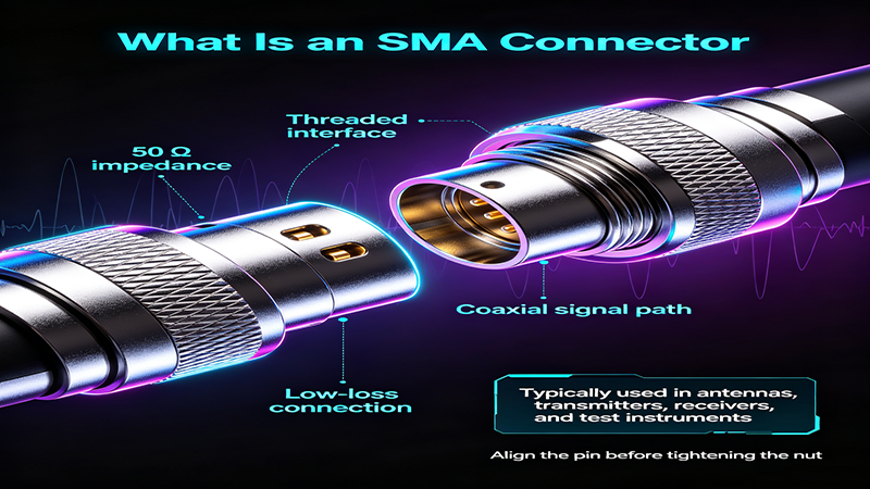
The SMA connector is one of the most widely used RF connectors in the microwave industry. Featuring a threaded coupling mechanism and a 1/4-36 thread, SMA connectors are designed for semi-rigid and flexible coaxial cables with 50-ohm impedance. Their compact size and reliable performance up to 18 GHz (with precision versions extending to 26.5 GHz) make them ideal for a vast range of applications.
Impedance: 50Ω | Frequency: DC–18 GHz
Thread: 1/4-36 UNS, Coupling: Threaded, Durability: 500+ mating cycles
Wi-Fi routers, GPS receivers, microwave test equipment, cellular base stations, military radar systems.
The BNC connector is characterized by its quick-connect bayonet coupling mechanism, which provides secure connection with a simple quarter-turn motion. BNC connectors are available in both 50-ohm and 75-ohm versions and are widely used in video, broadcast, and test equipment applications. Their frequency range is typically limited to 4 GHz, making them unsuitable for high-frequency microwave work.
Impedance: 50Ω / 75Ω | Frequency: DC–4 GHz
Coupling: Bayonet, Durability: 500+ mating cycles, Quick connect/disconnect
CCTV systems, broadcast video equipment, oscilloscopes, signal generators, legacy networking equipment.
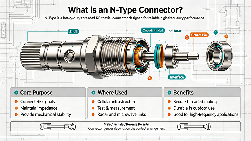
The N-Type connector is a rugged, weatherproof RF connector designed for medium to high-power applications. Its threaded coupling and robust construction provide excellent durability and water resistance when properly sealed. N-Type connectors are available in both 50-ohm and 75-ohm versions and operate reliably up to 11 GHz in standard configurations, with precision versions extending to 18 GHz.
Impedance: 50Ω / 75Ω | Frequency: DC–11 GHz (up to 18 GHz)
Thread: 5/8-24, Coupling: Threaded, IP67 rated options, High power capacity
Cellular base stations, outdoor antennas, broadcast transmitters, radar systems, industrial RF equipment.
The TNC connector is a threaded version of the BNC connector, designed to address the vibration and connection reliability issues of bayonet coupling in demanding environments. TNC connectors maintain the same impedance characteristics as BNC but offer superior mechanical stability, making them suitable for mobile and aerospace applications.
Impedance: 50Ω / 75Ω | Frequency: DC–11 GHz
Thread: 7/16-28, Coupling: Threaded, Vibration-resistant, 500+ mating cycles
Avionics, military communications, mobile radio systems, GPS antennas, aerospace telemetry.
The MCX connector is a micro-miniature RF connector featuring a snap-on coupling mechanism. With its extremely compact size (30% smaller than SMB connectors), the MCX is ideal for high-density applications where board space is at a premium. Despite its small size, it provides reliable performance up to 6 GHz.
Impedance: 50Ω / 75Ω | Frequency: DC–6 GHz
Coupling: Snap-on, Compact size, 500+ mating cycles, PCB mount options
GPS modules, Bluetooth devices, portable electronics, automotive telematics, compact test equipment.
The SMP connector is a high-frequency push-on connector designed for board-to-board and cable-to-board applications in dense microwave assemblies. Its unique design allows for axial and radial misalignment compensation (up to 0.5mm radial, 0.25mm axial), making it invaluable in multi-port phased array systems and high-density interconnect applications.
Impedance: 50Ω | Frequency: DC–40 GHz
Coupling: Push-on, Blind-mate capable, Misalignment tolerant, 100+ mating cycles
5G base stations, phased array antennas, satellite payloads, high-density RF modules, military electronics.
The following comparison chart provides a quick reference for the most commonly used RF connector types, their key specifications, and typical applications. Use this chart to narrow down your connector selection based on your specific requirements.
| Connector Type | Impedance (Ω) | Max Frequency (GHz) | Coupling | Typical Applications |
|---|---|---|---|---|
| SMA | 50 | 18 (26.5 precision) | Threaded | Wi-Fi, GPS, Test Equipment, Military |
| BNC | 50 / 75 | 4 | Bayonet | Video, Broadcast, Oscilloscopes |
| N-Type | 50 / 75 | 11 (18 precision) | Threaded | Base Stations, Antennas, High-Power RF |
| TNC | 50 / 75 | 11 | Threaded | Avionics, Military, Mobile Radio |
| MCX | 50 / 75 | 6 | Snap-on | GPS, Bluetooth, Portable Electronics |
| SMP | 50 | 40 | Push-on | 5G, Phased Array, Satellite |
| SMB | 50 / 75 | 4 | Snap-on | Telecom Equipment, Industrial RF |
| F-Type | 75 | 3 | Threaded | CATV, Satellite TV, Broadband |
| UHF | 50 | 0.5 | Threaded | Amateur Radio, Legacy Equipment |
| 2.92mm (K) | 50 | 40 | Threaded | Millimeter-wave, Test & Measurement |
Selecting the correct RF connector for your application requires careful consideration of multiple factors. Follow this structured approach to ensure optimal performance and reliability.
The operating frequency is the most critical factor in connector selection. The connector must maintain stable impedance and low insertion loss across the entire operating frequency band. As a rule of thumb, select a connector rated for at least 20% higher than your maximum operating frequency to account for temperature variations and manufacturing tolerances.
Ensure the connector impedance matches your system impedance. Using a 75-ohm connector in a 50-ohm system (or vice versa) will cause significant signal reflections and degraded performance. Most RF systems operate at 50 ohms, while video and CATV systems typically use 75 ohms.
For high-power applications, select connectors with larger center conductor diameters and robust dielectric materials. N-Type and 7/16 DIN connectors are excellent for high-power transmission, while micro-miniature connectors like MCX and SMP are not suitable for power levels above a few watts.
Consider temperature extremes, humidity, vibration, and exposure to corrosive environments. For outdoor or harsh environments, choose connectors with IP-rated sealing, corrosion-resistant plating (gold or silver), and threaded coupling mechanisms.
In high-density applications such as 5G arrays or portable devices, space is at a premium. Micro-miniature connectors like MCX, MMCX, and SMP offer excellent performance in compact form factors. However, smaller connectors typically have lower power handling and reduced mechanical durability.
Different industries have distinct requirements that influence RF connector selection. Understanding these application-specific needs helps ensure optimal system performance.
The rapid deployment of 5G networks has driven demand for high-frequency connectors capable of operating at mmWave frequencies (24 GHz, 28 GHz, 39 GHz bands). N-Type and 7/16 DIN connectors remain standard for base station antenna connections, while SMP and SMPM connectors are increasingly used in active antenna arrays and massive MIMO systems where board-level density is critical.
Military and aerospace applications demand the highest reliability under extreme conditions. TNC and N-Type connectors are preferred for their vibration resistance and robustness. SMA connectors are widely used in radar and electronic warfare systems, while precision connectors like 2.92mm and 2.4mm are essential for satellite communications and missile guidance systems.
The broadcast industry relies heavily on 75-ohm BNC connectors for video signal distribution in studios and production facilities. For outdoor broadcast and ENG (Electronic News Gathering) applications, N-Type connectors with weatherproof seals are commonly used for antenna connections and microwave links.
Test equipment requires precision connectors with excellent repeatability and low insertion loss. SMA and 3.5mm connectors are standard on most vector network analyzers and spectrum analyzers. For high-frequency measurements above 40 GHz, 2.92mm and 1.85mm precision connectors are essential. Calibration kits typically use precision versions of these connectors with tight tolerance specifications.
50-ohm connectors are designed for RF and microwave signal transmission where power handling and low loss are priorities. They are used in telecommunications, military, and test equipment. 75-ohm connectors are optimized for low-attenuation applications like video distribution and CATV systems. While they may look similar in some cases, the internal dimensions differ, and they should not be interchanged without proper adapters.
Standard SMA connectors are rated to 18 GHz. However, precision SMA connectors with tighter tolerances can operate up to 26.5 GHz. For frequencies above 26.5 GHz, you should consider 3.5mm, 2.92mm (K), or 2.4mm connectors, which offer better performance at millimeter-wave frequencies.
SMB (Sub-Miniature B) and MCX (Micro Coaxial) connectors are both snap-on coupling designs, but MCX connectors are approximately 30% smaller than SMB connectors. MCX is designed for higher density applications and operates up to 6 GHz, while SMB is typically limited to 4 GHz. Both are available in 50-ohm and 75-ohm versions.
Standard RF connectors are typically rated for 500 mating cycles, though this varies by connector type and quality. Precision test connectors may have lower cycle ratings (100-200 cycles) due to tighter tolerances, while ruggedized connectors like N-Type and 7/16 DIN can support 500+ cycles when properly maintained. Always check manufacturer specifications for your specific connector model.
For outdoor antenna installations, N-Type connectors with IP67 weatherproof ratings are the industry standard. They provide excellent moisture resistance when properly sealed with weatherproofing tape or heat-shrink tubing. 7/16 DIN connectors are also used for high-power outdoor installations. Both offer threaded coupling for vibration resistance and robust construction.
High-tech Enterprise, Feifeng Talent
Chief Engineer Wang graduated with a master's degree in high-power microwave from the Institute of Electronics, University of Chinese Academy of Sciences.
View Full Profile