






RF Test System Design: A Practical Guide to Signal Routing and Switching
What Makes a Good RF Test System?
An RF test system — whether a one-off lab setup or a production automated test rack — must deliver three properties above all: reliability, repeatability, and speed. The test rack should produce identical results on identical devices across days and operators, and it should do so in seconds, not minutes.
Reliability means the test system runs continuously without unexpected downtime. Production lines lose thousands of dollars per minute when a tester fails; reliability is non-negotiable. Repeatability means the same DUT tested twice produces the same numbers within the measurement uncertainty. Speed means the test runs in the minimum time consistent with the first two properties.
These goals shape every aspect of test system design — component selection, cabling, software architecture, calibration, and maintenance. The sections below walk through each in detail.
Block Diagram First
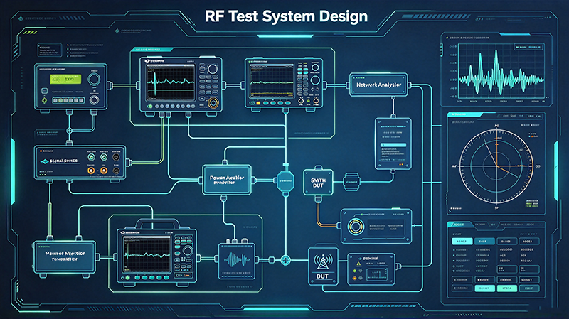
Before buying a single cable or instrument, sketch the signal flow on paper. Start with the device under test (DUT) and trace every signal path to its instrument or load. Identify where switches go, where attenuators go, where filters and amplifiers sit, and where calibration planes live.
A complete block diagram should show: every instrument input/output, every cable run with its type and length, every switch and its state under each test condition, every calibration plane, and the path of any DC bias or control signals. Once the block diagram is correct, the bill of materials is essentially a list of components needed to implement it.
Get the block diagram reviewed by another engineer before purchasing. The cost of a wrong cable or wrong connector is small; the cost of discovering six months into production that your test rack cannot measure what you need is enormous.
Switching Architecture
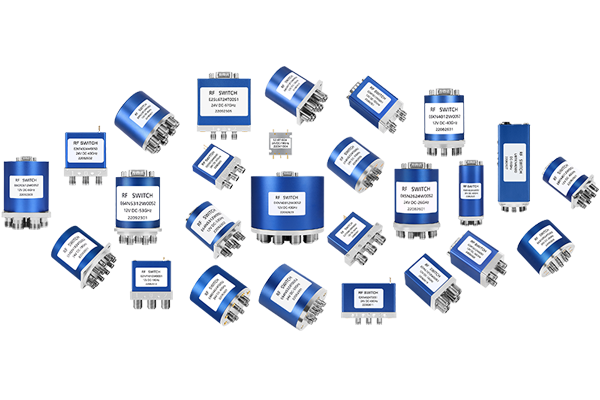
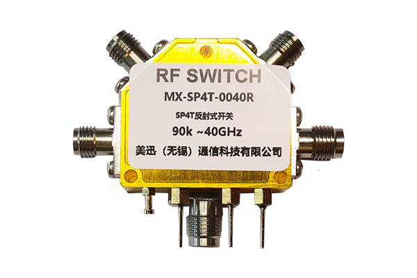
Choose between a 1-to-N distribution switch (one source distributed to many DUTs sequentially) and an M-to-N matrix (any DUT to any instrument at any time). For bench testing one device, a 1-to-N switch is enough. For ATE with multiple devices under test or multiple instruments, a matrix is almost always the right answer.
Within the matrix, full-crossbar gives maximum flexibility at the highest cost; blocking reduces cost but limits simultaneous paths. For most production testers, full-crossbar with cold-switching is the standard architecture.
Plan for expansion. A 4×4 matrix that is 70% full is a problem; a 4×4 matrix that is 30% full can grow. Buy larger than you need today.
Calibration
Calibrate at the DUT reference plane using a calibration kit — SOLT (Short-Open-Load-Thru) for coaxial, TRL (Thru-Reflect-Line) for microstrip, and waveguide-TRS for waveguide. The calibration removes the test cables, connectors, and any fixtures from the measurement, so what you measure is exactly the device under test.
Calibrate daily in production, or after every cable bend, or after every connector mate. Calibration drift of a few tenths of a dB is normal over a day; uncorrected drift of 1 dB will ruin measurement repeatability.
Use a calibration verification standard after each calibration — a known-good device (a 3 dB pad, a through, or a verified airline) that you measure to confirm the calibration is still valid. If the verification fails, recalibrate before running tests.
Cabling and Connectors
Use phase-stable cables for any path that requires amplitude or phase accuracy. Phase-stable cable uses a foamed dielectric that does not deform when the cable is bent, ensuring consistent phase delay. Standard coax cable changes phase with flexure and should not be used for phase-sensitive measurements.
Torque every connector to its specification: 8 in-lbs for SMA, 12 in-lbs for Type-N, 4 in-lbs for 3.5 mm and 2.92 mm. Use a calibrated torque wrench — hand-tight is not enough and over-tight is damaging. Inspect connectors with a microscope or magnifier every 100–500 cycles.
Label every cable. Both ends. With its length and purpose. Six months after installation, no one will remember which cable goes where without labels.
Software and Triggering
Trigger from a single master clock or trigger bus. Every instrument and every switch should be triggered from the same source to ensure that switch transitions happen in a deterministic, known time relationship to measurements.
Synchronize switch state with instrument acquisition. The most common test-system bug is a measurement taken during a switch transition — the result is meaningless and corrupts data. The test software must wait for the matrix to settle (typically 20–50 ms after a switch command) before triggering the instrument acquisition.
Use the standard SCPI command set for instruments and IVI drivers where possible. Custom control protocols increase maintenance cost and lock you to a single vendor.
Maintenance
Schedule connector inspection, switch cycle counting, and cable replacement on a calendar — not on a 'when I notice' basis. A test rack that has not been calibrated in six months is not the test rack you designed; its accuracy has drifted by 1–2 dB and its connectors have accumulated wear.
Keep a maintenance log. Every calibration, every connector inspection, every switch cycle count, every cable replacement should be timestamped and recorded. When results start to drift mysteriously six months later, the log tells you which component is aging.
Stock spares. Have at least one spare switch, one spare attenuator, one spare set of cables, and one spare calibration kit. Production lines cannot wait two days for a delivery when a critical component fails.
Common Mistakes in RF Test System Design
1. Skipping calibration at the DUT reference plane — measuring at the instrument reference plane instead.
2. Using hand-tight connectors on precision test cables.
3. Hot-switching RF power through switches not rated for hot switching.
4. Using unshielded or poorly shielded cables for sensitive measurements.
5. Routing cables near switching power supplies or digital logic without filtering.
6. Failing to ground the test rack to a single low-impedance ground point.
7. Using long, lossy cables between the matrix and the DUT.
8. Trusting instrument readings without a calibration verification standard.
Frequently Asked Questions
Q: How often should I calibrate? A: Daily in production, or after any cable/connector change. For lab work, weekly is usually sufficient.
Q: What is the difference between cold and hot switching? A: Cold switching means no RF power is present during the switch transition; hot switching transitions while RF is present. Most switches are rated for one or the other.
Q: How do I know if my test rack needs maintenance? A: Calibration verification standards that begin to drift, connectors that fail visual inspection, or switch cycle counters exceeding 80% of rated life.
Q: Should I use USB or Ethernet for instrument control? A: USB for benchtop one-off testing; Ethernet for production racks where multiple test stations need to share instruments.
Engineering Notes from Years of Building Test Racks
After building dozens of RF test systems for cellular, Wi-Fi, satellite, and aerospace customers, a few patterns emerge. The most reliable test racks share these characteristics: phase-stable cables throughout (even where phase is not measured, because phase-stable cable has more consistent loss and impedance); daily automated calibration with verification; a single master trigger source for all instruments and switches; full electrical schematics in the rack documentation; and a spare parts kit pre-staged at the rack.
The least reliable test racks are those built by engineers who treated them as one-off lab experiments rather than production tools. Cables from different manufacturers, connectors torqued by hand, no calibration verification, no maintenance log, and no documentation. These racks always fail in production — usually within the first month.
Case Study: Aerospace Test Rack Redesign
An aerospace test rack for satellite payload testing was redesigned after 5 years of operation revealed cumulative downtime of 30% (5 weeks of every quarter). The redesign included: replacing all hand-torqued connectors with calibrated torque-wrenched assemblies; replacing all cables with phase-stable equivalents from a single vendor; adding automated daily calibration verification; documenting every cable with printed labels at both ends; training two operators on preventive maintenance procedures. The redesigned rack achieved 99.5% uptime over the next 3 years — a 14× reduction in downtime, achieved entirely through better design discipline rather than better components.
Closing Thoughts
A great RF test system is not the one with the best components — it is the one with the best discipline. Daily calibration, careful connector care, consistent cable management, and detailed documentation will outperform a more expensive but casually maintained system every time. The investment in discipline pays for itself many times in reduced downtime, faster troubleshooting, and more reliable measurements.
Industry Applications and Use Cases
Across telecommunications, aerospace, defense, medical imaging, and automotive radar, the concepts covered in this guide show up in every RF design. From 5G base stations deploying massive MIMO antenna arrays with dozens of Wilkinson dividers per panel, to satellite payloads where every decibel of link budget determines the success of a multi-million-dollar mission, the principles remain the same: measure carefully, design with margin, and verify with the right instrument.
Medical applications add another wrinkle: MRI machines operate at the Larmor frequency of hydrogen (42.58 MHz/Tesla) and require extraordinarily low noise and high stability. Test systems for MRI receivers must minimize cable loss between the imaging coil and the low-noise preamplifier — often mounted directly on the coil housing — because every dB of loss degrades diagnostic image quality. The same matching, cabling, and LNA placement principles apply.
Automotive radar at 77 GHz is one of the fastest-growing RF domains. Each modern car may contain 5–10 mmWave radar units for adaptive cruise control, blind-spot detection, and automated emergency braking. These radar modules contain calibrated Wilkinson dividers, matched patch antennas, beam-steering phase shifters, and integrated FMCW synthesizers — all built on low-cost PCB substrates and tested in production at volumes exceeding 100 million per year. The principles taught in this guide are what make that volume manufacturing possible.
Advanced Design Considerations
Beyond the basics covered above, several advanced topics deserve attention as your designs mature. Multi-physics simulation — coupling electromagnetic, mechanical, and thermal effects in a single simulation — is increasingly important at mmWave frequencies where small dimensional changes from thermal expansion can shift the operating frequency. Tools like ANSYS HFSS, CST Studio Suite, and Cadence Clarity now include multi-physics capabilities that integrate structural and thermal solvers with the RF simulator.
Machine learning is beginning to appear in RF design. Surrogate models trained on simulation data can predict S-parameters 1000× faster than running the full EM simulation, enabling design space exploration that was previously impossible. Tools like Google Brain's RF antenna design work and Cadence's Cerebrus are early examples of where the field is heading. For now, these tools augment rather than replace the engineer's judgment — they accelerate iteration but the final design still needs to be understood, verified, and signed off by an experienced engineer.
Standards, Compliance, and Regulation
Every RF system must comply with applicable regulatory standards. In the United States, Part 15 of the FCC rules governs intentional radiators and unintentional emissions. The European Union's Radio Equipment Directive (RED) does similar work. Specific applications have additional standards: ETSI EN 301 893 for 5 GHz Wi-Fi, ETSI EN 302 500 for UWB, and many others. Military and aerospace applications have additional standards: MIL-STD-461 for EMI, MIL-STD-810 for environmental, and MIL-STD-1540 for product assurance.
Compliance testing is a discipline of its own. Compliance test labs use specialized instruments (spectrum analyzers with quasi-peak detectors, EMI receivers calibrated to CISPR standards) and follow specific procedures. The measurement uncertainty of compliance tests is typically ±3 to ±6 dB — much wider than production test measurements, but required for regulatory acceptance. Plan for compliance testing early in your design cycle; retrofitting a product to meet EMI requirements after the design is finalized is expensive and time-consuming.
Career and Skill Development in RF Engineering
RF engineering is a deep specialty with strong demand and excellent compensation. The barrier to entry is high: unlike software, you cannot iterate in seconds, and the cost of mistakes is paid in physical hardware. Yet for engineers who take the time to develop intuition, RF offers some of the most satisfying engineering work available — every component choice has a measurable effect, and every measurement reveals something about the physical world.
For those starting out, build a home lab. Even a modest setup with a cheap SDR (RTL-SDR, HackRF, or Airspy), a few antennas, and some cables will let you explore the RF spectrum in ways that no simulator can. Add a low-end spectrum analyzer (Rigexpert, TinySA) when you can afford it, and a used VNA from eBay when the budget allows. The hands-on experience with real signals, real cables, and real instruments is what builds intuition that no textbook can provide.
Stay current by reading industry publications (Microwave Journal, RF Globalnet, Microwaves & RF), attending conferences (IMS, EuMW, IEEE MTT-S), and joining professional communities (IEEE MTT-S, ACM SIGCOMM for networking RF). The field evolves rapidly — mmWave 5G, satellite internet, and automotive radar were niche markets 10 years ago and are now mainstream. The engineers who built those markets started by mastering exactly the fundamentals covered in this article.
About the Author — MeiXun Team
Chief Engineer Wang
High-tech Enterprise, Feifeng Talent
Chief Engineer Wang graduated with a master's degree in high-power microwave from the Institute of Electronics, University of Chinese Academy of Sciences.
View Full Profile- RF Switch Circuit Diagram
- RF Switch
- Ohm's Law
- dBm to Watt
- mW to dBm
- Wavelength to Frequency
- RF Connector
- SMA Connector
- RF Switch Module
- RF Coupler
- RF PIN Switch
- Microwave Coaxial Switch
- PIN Switch
- Coaxial RF Switch
- Waveguide Switch
- Microwave Switch
- Low Noise Amplifier
- PIN Diode Switch
- Coaxial Switch
- RF Microwave Switch
- SPST Switch