

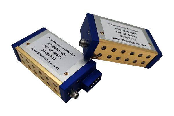
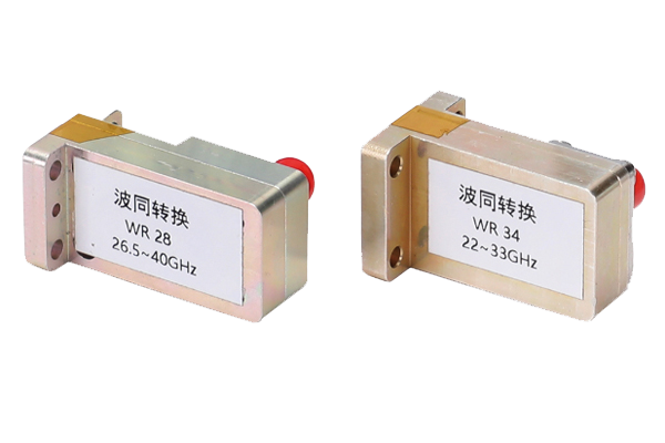
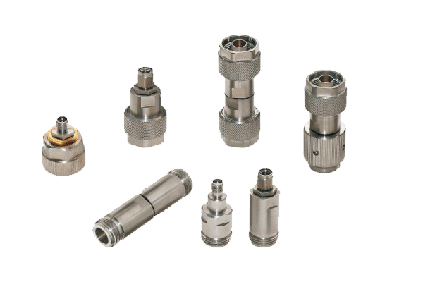
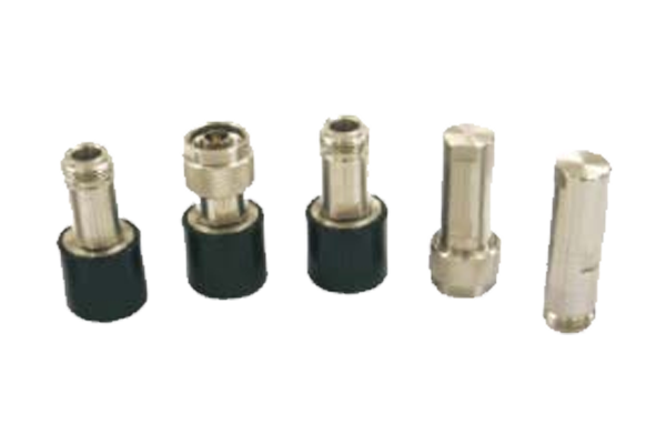
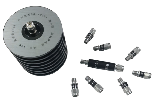
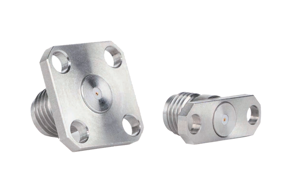
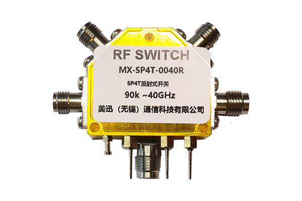
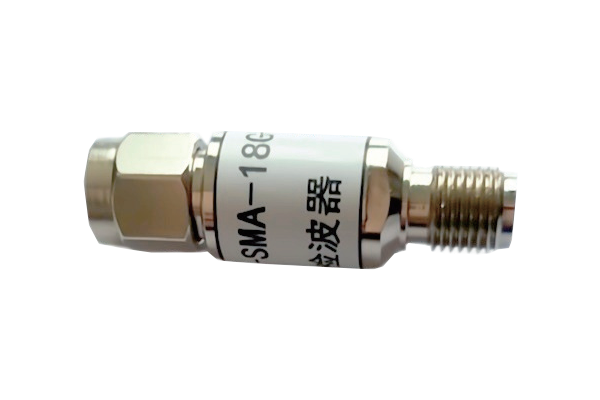
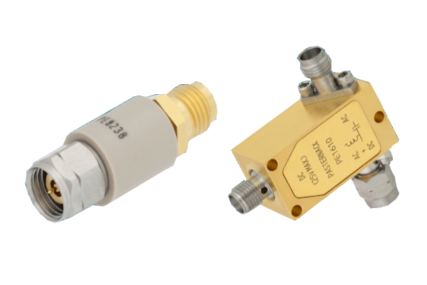
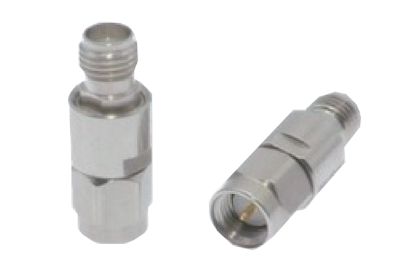
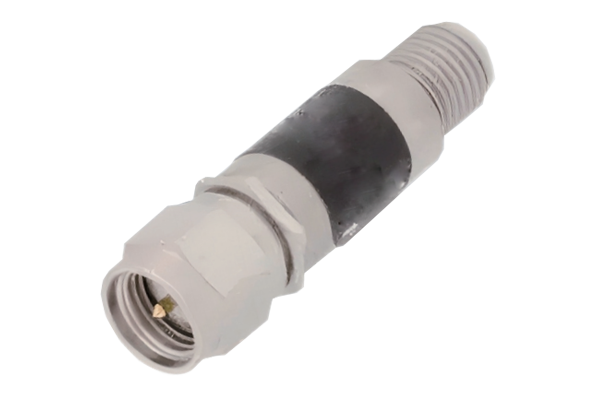
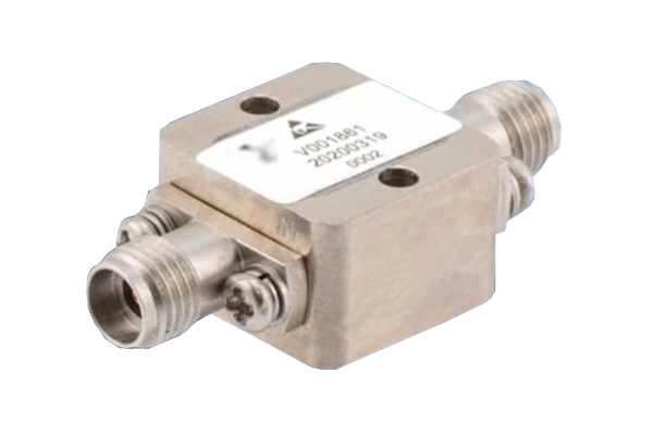
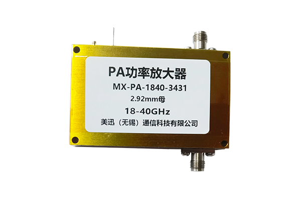
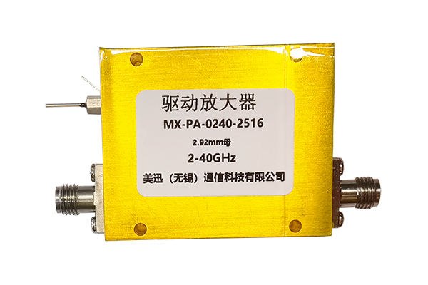



RF signal distortion can significantly affect the performance of wireless communication systems, radar equipment, satellite links, test instruments, and microwave electronics.
Sep 29 ,26


5G communication testing, wireless terminal automated testing
Aerospace communication systems
Precision measurement equipment, radio frequency signal control of radar transmitters
Communication and navigation systems
Optical communication module-related testing
Interconnection of wireless communication base stations
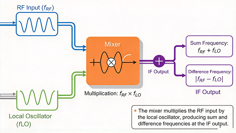
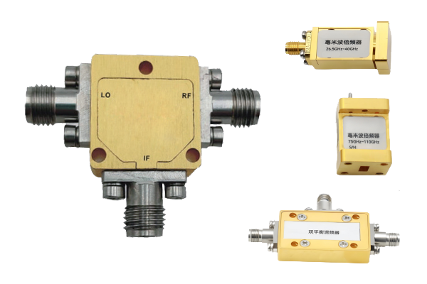
An RF mixer is a three-port RF component that converts energy at one frequency into energy at a different frequency. It is a fundamental building block in every RF system that needs to change frequency, including superheterodyne receivers, transmitters, frequency synthesizers, radar front ends, satellite transponders, cellular base stations, and spectrum analyzers.
Unlike a passive filter or attenuator, a mixer is fundamentally a nonlinear component. It exploits nonlinearity deliberately: when an RF signal is multiplied by a local oscillator signal, the product contains new frequencies that were not present in either input. Those new frequencies are the sum and difference combinations, and only one of them is desired.
A mixer has three functional ports:
Some mixers also expose an isolated LO port or a second output port for LO monitoring and power feedthrough measurement. The isolated LO port is internally separated from the RF and IF paths, allowing the local oscillator to be connected without unwanted coupling.
Every mixer is reciprocal. If the IF signal is fed into the IF port and the LO into the LO port, the RF port produces the upconverted signal. This reciprocal property is what allows a single bidirectional mixer design to serve both transmit and receive chains.
The operating principle of an RF mixer is frequency multiplication, commonly implemented as a trigonometric identity. When a cosine is multiplied by another cosine, the product contains a constant term and a term at twice the frequency.
Expressing this in the standard mixing formula:
The key insight is that only the LO frequency determines the output frequency. The RF input contributes to the arithmetic, but the synthesizer controls the LO. This is what makes a mixer the mechanism for channel selection and for tuning across a wide band with a single fixed-frequency filter downstream.
The multiplication behavior is achieved with a nonlinear device. In a passive mixer, this is a Schottky diode junction whose current-voltage relationship contains a second-order term. When the RF signal and LO are applied to the same nonlinear junction, the junction's nonlinearity produces the sum and difference products automatically.
In an active mixer, the switching action of a transistor differential pair driven by the LO performs a similar function, but with the added benefit of amplification. The transistor pair alternately connects and disconnects current paths, effectively performing high-speed multiplication.
Because the mixer output contains both the sum and difference products, plus a host of harmonics and intermodulation products, a bandpass filter is always placed after the IF port to select the desired product and reject everything else. Without this filter, the downstream receiver would be unable to distinguish the desired signal from spurious products.
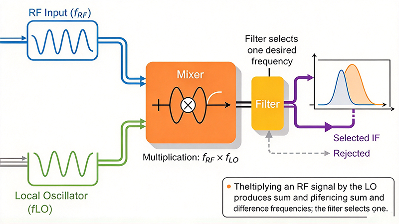
The local oscillator is the reference that sets the output frequency. It is typically generated by a frequency synthesizer or a crystal oscillator with a multiplier chain. The LO signal must meet three requirements:
Two tuning schemes are common. With high side injection, the LO sits above the RF and the IF is the difference. With low side injection, the LO sits below the RF and the IF is the difference. The choice affects the required filter selectivity, the achievable image rejection, and the frequency planning of the synthesizer.
| Aspect | High Side Injection | Low Side Injection |
|---|---|---|
| LO frequency | fRF + fIF | fRF − fIF |
| LO frequency range | Higher than RF | Lower than RF |
| Synthesizer tuning ratio | Fixed offset, slightly wider range | Fixed offset, sometimes simpler |
| Image frequency location | Below the RF input | Above the RF input |
| Image filter position | Easier in many architectures | Often requires a higher cutoff filter |
Passive mixers require LO power, typically between 0 dBm and 10 dBm. The optimum level maximizes conversion efficiency and linearity. Too little LO drive degrades conversion loss and raises LO feedthrough. Too much LO drive increases DC power consumption and can cause overheating or parameter drift. Active mixers typically require more LO drive than passive designs.
Frequency conversion happens in two directions, and the choice affects filter design, gain planning, and system architecture.
Downconversion moves a higher frequency signal to a lower IF. This is the standard receiver architecture because it keeps the IF bandwidth narrow and filter requirements achievable. Downconversion is used in superheterodyne receivers, spectrum analyzers, and software-defined radio front ends.
The main advantage is that the IF filter can be a narrow, high-order filter that selects one channel while rejecting adjacent channels and images. The main disadvantage is that the image frequency must be filtered out, which requires either a preselector filter or careful frequency planning.
Upconversion moves a lower frequency signal to a higher output frequency. This is used in transmitters, frequency translation stages, and upconverters in phased array systems. Upconversion is also used when a low-frequency signal must be routed to a common high-frequency backplane.
Some receivers use two mixers in sequence to achieve high selectivity with practical filters. The first mixer converts to a high IF where a high-order filter can reject the image, and the second mixer converts down to a low IF for digitization. This double conversion architecture is common in high-performance receivers and in wideband sweep receivers.
Any mixer exhibits a fundamental ambiguity: two different RF frequencies will produce the same IF. These two frequencies are the desired signal and the image.
For example, if the LO is 100 MHz and the IF is 10 MHz, both a 90 MHz input and a 110 MHz input produce a 10 MHz IF. The two are indistinguishable at the IF port.
If the 110 MHz signal is the desired one and the 90 MHz signal is an interferer, the interferer will appear directly in the output band and degrade the measurement or desensitize the receiver. This is called image response.
RF mixers are classified by the nonlinear mechanism, the topology, and whether they provide gain. The main categories are described below.
Passive mixers use Schottky diodes as the nonlinear element. They require no DC power and offer excellent linearity, wide bandwidth, and low cost. The trade-off is conversion loss, typically 6 to 10 dB. Passive mixers are the traditional choice for wideband receiver front ends and for instrumentation.
Active mixers incorporate amplifying or switching devices, so they can provide conversion gain, meaning conversion loss may be negative. Gilbert cell mixers are the most common active topology, using three transistor differential pairs. Active mixers integrate well with CMOS processes and offer excellent LO isolation, but consume DC power and can be less linear than passive designs at high drive levels.
A balanced mixer uses a symmetrical circuit with two diodes and two hybrid couplers or transformers. A double balanced mixer uses four diodes in a ring between two baluns. Because the structure is fully symmetrical, it provides high isolation between all ports, wide bandwidth, and excellent rejection of even-order harmonics. Double balanced mixers are the preferred architecture for high-performance applications.
A subharmonic mixer samples the RF signal every second half cycle of the LO, effectively dividing the LO frequency by two. This halves the required synthesizer output frequency, which simplifies wideband tuning and reduces phase noise multiplication. Subharmonic mixers are common in wideband sweep receivers, phased array systems, and harmonic mixers used in harmonic measurements.
Harmonic mixers intentionally use higher harmonics of the LO rather than the fundamental. The n-th harmonic mixer uses n × fLO, so with an LO at 100 MHz, a second harmonic mixer responds to RF near 200 MHz. Harmonic mixers are widely used in frequency extenders for spectrum analysis into the millimeter-wave bands and in low-cost harmonic detector circuits.
Several specialized mixer families serve particular needs:
| Mixer Type | Conversion Loss | Isolation | Bandwidth | Power | Typical Use |
|---|---|---|---|---|---|
| Passive diode, single balanced | 6 – 10 dB | 15 – 30 dB | Very wide | None | Wideband receivers |
| Passive diode, double balanced | 6 – 9 dB | 25 – 40 dB | Wide | None | Instrumentation, high directivity |
| Gilbert cell, active | −5 to +5 dB | 20 – 35 dB | Moderate | 10 – 100 mW DC | 5G, Wi-Fi, SDR |
| Subharmonic, passive | 8 – 12 dB | 15 – 25 dB | Moderate | None | Wideband sweep, phased array |
| Harmonic, waveguide | 10 – 20 dB | 20 – 35 dB | Narrow | None to high | mmWave extenders, harmonic detection |
| Image-rejecting, active | 2 – 8 dB | 25 – 40 dB | Moderate | 20 – 200 mW DC | Zero-IF, direct conversion |
Datasheets specify mixers using a consistent set of parameters. The table below explains what each one means and why it matters.
| Parameter | What It Means | Why It Matters |
|---|---|---|
| Frequency range | RF, LO, and IF ranges over which performance is specified | Must cover all three ports; a mixer is only guaranteed inside the specified three-dimensional box |
| Conversion loss | Ratio of RF input power to IF output power in dB | Directly reduces receiver sensitivity and must be budgeted in the link loss |
| LO-IF isolation | Rejection of LO power appearing at the IF port | High LO leakage can desensitize the IF chain or create false readings |
| LO-RF isolation | Rejection of LO power appearing at the RF port | Critical in transmit chains to prevent LO radiation back into the antenna |
| RF-IF isolation | Feedthrough of the RF signal straight to the IF port | Poor feedthrough means the desired signal and leakage arrive together |
| Image rejection | Suppression of the undesired frequency that maps to the same IF | Determines receiver selectivity without a large preselector filter |
| P1dB | Input power at which conversion gain drops 1 dB | Limits the maximum signal the receiver chain can handle linearly |
| IP3 | Third-order intercept point, usually reported as OIP3 | Determines interference tolerance and spurious performance |
| LO drive level | Required LO power for specified performance | Insufficient or excessive LO drive degrades all other parameters |
| LO-RF vs LO-IF bandwidth | Frequency range over which LO power is accepted | Must match the synthesizer output range exactly |
| Passband ripple | Variation in conversion loss across the band | Affects flatness requirements in wideband instruments |
| Operating temperature | Temperature range for rated performance | Performance degrades and LO frequency drifts outside this range |
Conversion loss is the most frequently misunderstood mixer specification. It is defined as the loss from the RF input port to the IF output port, measured at a specific RF input power and a specific LO drive level.
Two aspects of this definition matter in practice. First, conversion loss is not constant across the frequency band. It typically worsens toward band edges and may ripple by several dB in the middle of the band. Second, it depends on the LO drive level. Because passive mixers rely on the switching action of the diodes, an under-driven LO produces higher conversion loss.
Passive mixers have no active gain mechanism. Energy is removed from the RF path in three ways: the nonlinear conversion process itself, mismatch and reflection at the ports, and ohmic loss in the conductors and the diode junction. A well-designed passive mixer achieves 6 dB conversion loss, which is the theoretical minimum for a passive 3 dB-coupled structure.
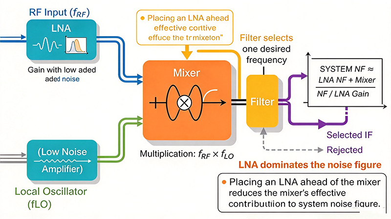
In a receiver budget, the mixer conversion loss sits between the antenna and the first IF amplifier. Since it comes before the first gain stage, it cannot be recovered. The sensitivity impact is direct: adding 6 dB of mixer loss before an amplifier means the amplifier must supply 6 dB more gain to achieve the same overall noise figure.
Isolation describes how well the mixer prevents a signal applied at one port from appearing at another. Because a mixer is a physically coupled structure, some signal always leaks between ports, and the isolation specification quantifies this leakage.
In a transmit chain, the LO feeds the mixer to generate the transmit signal. Any LO power that leaks back out the RF port is radiated by the antenna. This leakage can desensitize nearby receivers and create interference in adjacent channels. Good transmitters require high LO-RF isolation, typically above 30 dB, and often add an explicit LO filter at the RF port.
LO power leaking to the IF port is the most damaging form of feedthrough. It appears as a strong spurious tone in the IF bandwidth and can desensitize the IF chain or produce false readings in measurement equipment. Double balanced mixers typically provide 30 to 40 dB of LO-IF isolation.
The desired RF signal is converted to IF, so RF power appearing at the IF port is a form of feedthrough rather than leakage. It is normally small because the conversion process intentionally removes most of the RF energy. However, in very high frequency or very wideband designs, direct RF-to-IF feedthrough can exceed the desired IF signal and must be filtered.
Mixer linearity determines how well the mixer handles strong signals without generating spurious products. Two parameters define it.
The 1 dB compression point is the input power at which the conversion gain drops 1 dB below its linear value. Because passive mixers are lossy, the P1dB is usually referenced to the RF input. Typical values range from −5 dBm for precision instrumentation mixers to +10 dBm for high-power designs.
When two strong signals enter the mixer, they generate third-order intermodulation products at 2f₁−f₂ and 2f₂−f₁. The third-order intercept point is the input power at which the fundamental and third-order products would intersect. For passive mixers, IP3 is often around 10 to 20 dBm.
Mixer linearity determines the maximum dynamic range of the receiver. Two strong interferers entering the mixer produce intermodulation products that can fall in-band and mask weak desired signals. This effect is called blocking desensitization and is often the limiting factor in cellular base station receivers, where adjacent channel power can exceed the desired signal by 40 dB or more.
| Mixer Class | Typical P1dB | Typical IP3 | Application Emphasis |
|---|---|---|---|
| High-precision instrumentation | −2 to +3 dBm | +15 to +25 dBm | Linearity and flatness over bandwidth |
| General receiver | 0 to +5 dBm | +10 to +20 dBm | Balanced loss and linearity |
| High-dynamic-range receiver | +5 to +10 dBm | +20 to +30 dBm | Strong interferer rejection |
| Active CMOS mixer | −5 to 0 dBm | +5 to +15 dBm | Gain and integration |
| Waveguide mixer | +10 to +30 dBm | +30 to +45 dBm | High power and mmWave |
Beyond the desired sum and difference products, a mixer generates a family of unintended outputs at frequencies of the form n × fLO ± m × fRF, where n and m are small integers.
The most important spurious responses are:
Spurious responses are particularly problematic when the IF is low, because many harmonic combinations fall near the IF frequency. Designing the frequency plan so that no significant harmonic combination lands in the IF band is one of the most important steps in mixer selection.
For passive mixers, both the conversion loss and the linearity are functions of the LO drive level. This creates an important design tradeoff.
Systematic mixer selection avoids the most common integration mistakes. Follow this sequence.
When a mixer-based design underperforms, the cause is usually one of a small number of predictable issues.
Almost always caused by insufficient LO drive or by LO drive at the wrong frequency. Measure the LO power at the mixer LO port with a power meter, not at the oscillator output. Also confirm the LO frequency is within the specified range. A mixer driven outside its LO bandwidth will not perform as specified.
Verify that the preselector filter is before the mixer, not after. Confirm the filter is designed for the image frequency rather than the RF frequency. Also check that the preselector filter impedance matches the mixer input over the full band, since a mismatched filter degrades the effective rejection.
Check LO drive level first, since insufficient LO power degrades isolation. Then verify that the IF filter provides rejection at the LO frequency. Adding a simple low-pass or bandpass filter at the IF port can significantly suppress LO feedthrough without affecting the desired IF signal.
This is a frequency planning problem. Enumerate all n × fLO ± m × fRF combinations and check whether any land in the IF passband. In many cases the only fix is to change the IF frequency or the injection scheme.
Conversion loss and isolation both degrade as temperature changes, and the LO frequency itself drifts. In critical applications, specify the mixer across the full operating temperature range, and add temperature compensation in the synthesizer reference. Also check whether the LO buffer amplifier has adequate thermal headroom.
Excessive LO radiation from a transmit chain usually indicates insufficient LO-RF isolation or a missing LO filter. Add an explicit LO filter at the RF port and verify the isolation budget. In high-power systems, a diplexer or duplexer with harmonic filtering may be required.
Board parasitics and connector transitions typically add 0.5 to 2 dB of unexpected loss at microwave frequencies. Verify your PCB stackup matches the mixer evaluation board, check the quality of solder joints on the RF pads, and confirm that the transition from microstrip to the mixer's launch is properly designed.
The RF mixer is the component that makes frequency conversion possible, and its specifications determine the achievable sensitivity, selectivity, and dynamic range of the entire receiver or transmitter. Because a mixer's performance depends on four tightly coupled parameters, namely the frequency plan, conversion loss, isolation, and linearity, engineers should always evaluate them together rather than selecting on conversion loss alone.
Topology selection follows from the requirements. Passive diode mixers serve wideband and low-cost designs where linearity matters more than gain. Double balanced structures deliver the isolation and bandwidth needed for instrumentation and high-performance receivers. Gilbert cell active mixers integrate efficiently into CMOS transceivers for 5G, Wi-Fi, and SDR. Subharmonic and harmonic mixers solve frequency planning problems in wideband sweep and mmWave measurement. Waveguide mixers remain the only practical option at the highest frequencies and power levels.
Two design rules consistently produce the best results. First, place a low-noise amplifier ahead of the mixer whenever the system noise figure allows it, because mixer loss is unrecoverable once it occurs before the first gain stage. Second, perform the harmonic analysis before committing to a frequency plan, because spurious combinations that fall in the IF band are the most common cause of unexpected measurement errors and receiver desensitization.
For further technical reading, consult the IEEE Transactions on Microwave Theory and Techniques, the Microwave Journal, and application notes published by leading mixer and component manufacturers. For datasheet-driven selection across manufacturers, the dbspecMW catalog provides parametric search over frequency range, conversion loss, isolation, IP3, LO drive level, and package type.
Our engineering team can identify the optimal mixer topology for your frequency plan, isolation, linearity, and cost requirements, and provide parametric data across manufacturers.
Contact Our RF Engineers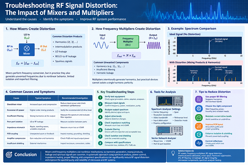
High-tech Enterprise, Feifeng Talent
Chief Engineer Wang graduated with a master's degree in high-power microwave from the Institute of Electronics, University of Chinese Academy of Sciences.
View Full Profile