


























A practical guide to designing RF test systems: signal routing, switching, calibration, and the small details that turn a fragile prototype into a reliable production tester.
Oct 20 ,26


5G communication testing, wireless terminal automated testing
Aerospace communication systems
Precision measurement equipment, radio frequency signal control of radar transmitters
Communication and navigation systems
Optical communication module-related testing
Interconnection of wireless communication base stations
A rotary switch is a multi-position switch that selects between several outputs by rotating a shaft. The shaft carries a wiper or cam that connects a common terminal to one of many fixed contacts. Common configurations include SP4T, SP12T, and multi-pole versions. Rotary switches offer precise indexing, mechanical durability, and clear tactile feedback — ideal for range selection, mode control, and industrial manual override.
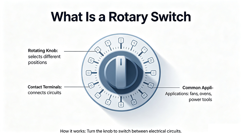
A rotary switch is an electromechanical switch whose position is selected by rotating its actuator. It typically consists of:
Each detent position corresponds to a unique electrical connection. Most rotary switches are designed to break before make or make before break depending on application requirements.
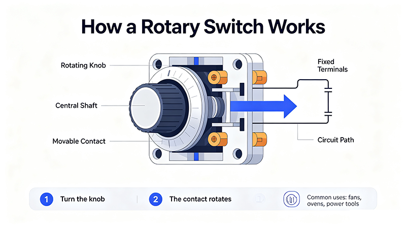
Rotating the shaft moves the wiper through a circular pattern of fixed contacts, selecting exactly one position at a time. The detent mechanism provides crisp tactile feedback at each step.
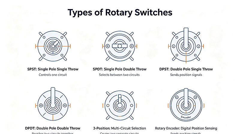
Common single-pole switch with 4 – 12 positions. Used for range selection on meters, mode switches on instruments, and small appliance controls.
Multiple decks stacked on a single shaft, switching several independent circuits simultaneously. Used in audio mixers and instrumentation.
Heavy-duty switch with cam-driven contacts for high current and high voltage. Used in motor starters, disconnect switches, and industrial control panels.
Compact through-hole or SMD-mounted rotary switch for printed circuit boards. Common in test equipment and consumer products.
Continuous-rotation digital device that outputs quadrature pulses. Used in volume knobs, motor feedback, and HMI controls. No detents.
Security rotary switch requiring a key for actuation. Used in access control panels and equipment interlocks.
Multi-deck switch built from stacked wafers. Each wafer adds another pole. Common in broadcast, audio, and industrial control.
Small wheel with numbers or symbols. Press-and-turn for each digit. Used in code-entry systems and timing controls.
| Specification | Meaning |
|---|---|
| Number of Positions | How many detent steps (3 – 12 typical) |
| Poles per Deck | Independent circuits per layer |
| Number of Decks | Layers stacked on one shaft |
| Contact Rating | Max voltage and current per pole |
| Contact Resistance | On-state resistance (< 50 mΩ typical) |
| Insulation Resistance | Off-state resistance between poles |
| Mechanical Life | Cycles before wear (10,000 – 100,000 typical) |
| Indexing Angle | Degrees between detents (15°, 30°, 45°, 60°) |
| Make-Before-Break / Break-Before-Make | Switching action type |
| Shaft Length / Thread | Mechanical mounting dimension |
| IP Rating | Sealing for dust/water |
| Code | Name | Function |
|---|---|---|
| SP3T – SP12T | Single-Pole, 3 to 12 Throw | One input, multiple outputs |
| DP3T – DP6T | Double-Pole variants | Two independent circuits |
| 3P4T, 4P3T | Three/Four-Pole variants | Multiple circuits simultaneously |
| Shorting / Non-shorting | Action type | Make-before-break or break-before-make |
| Aspect | Mechanical | Electronic (Solid-State) |
|---|---|---|
| Contacts | Physical wiper | MOSFET / analog switch |
| Life | 10k – 100k cycles | Billions of cycles |
| On Resistance | 10 – 50 mΩ | 0.1 – 10 Ω |
| Tactile Feedback | Yes, crisp detents | No |
| Power Handling | Up to several kW | Low (mW to a few W) |
| Bounce | Few ms (debounce needed) | None |
| Cost | Low | Low – moderate |
Rotary cam switches select HAND / OFF / AUTO modes, motor forward/reverse, and multi-speed settings. They are the standard for manual override in factory automation.
Mixers and amplifiers use rotary switches for input selection, gain staging, and routing. Multi-deck designs route balanced signals without cross-talk.
Multimeters, oscilloscopes, and signal generators use rotary switches to select voltage ranges, function modes, and trigger sources.
Climate controls, fan speeds, headlight modes, and 4WD selector dials rely on compact rotary switches for tactile user control.
Wafer switches select microphone inputs, monitor outputs, and routing in broadcast consoles. Long life and clean contact are essential.
Washing machines, ovens, range hoods, and ceiling fans use rotary switches for program and speed selection.
Key-operated rotary switches engage alarm systems, vault locks, and machinery interlocks.
Multi-position rotary switches are popular in custom audio gear, model railroad controls, and amateur radio antenna tuners.
A rotary switch is a multi-position switch operated by rotating a shaft. Each detent position connects a common terminal to one of several output contacts.
A rotary switch has detents and selects discrete positions. A rotary encoder is continuous-rotation, with no detents, and outputs quadrature pulses for digital feedback.
SP4T = Single-Pole, 4-Throw. The switch has one common input that can connect to one of four outputs at a time.
Rotary cam switches handle high currents and voltages in industrial motor control, disconnect switches, and manual starters.
Mechanical rotary switches typically last 10,000 to 100,000 cycles. Signal-level rotary switches tend to last longer than power-rated ones due to lower arcing.

High-tech Enterprise, Feifeng Talent
Chief Engineer Wang graduated with a master's degree in high-power microwave from the Institute of Electronics, University of Chinese Academy of Sciences.
View Full Profile