


























A high power waveguide switch is a critical microwave component designed to control the transmission path of high-frequency signals while handling high RF power levels.
Aug 03 ,26


5G communication testing, wireless terminal automated testing
Aerospace communication systems
Precision measurement equipment, radio frequency signal control of radar transmitters
Communication and navigation systems
Optical communication module-related testing
Interconnection of wireless communication base stations
Ka band waveguide switches are high-frequency microwave switching components designed to route electromagnetic signals between different waveguide paths. Operating in the Ka-band frequency region, typically around 26.5–40 GHz, these switches are widely used in satellite communications, radar systems, electronic warfare, aerospace test equipment, and high-frequency microwave networks.
Compared with conventional coaxial RF switches, a waveguide switch can provide excellent power handling, low insertion loss, high isolation, and stable performance at millimeter-wave frequencies. These characteristics make Ka band waveguide switches particularly useful when signal integrity and RF efficiency are critical.
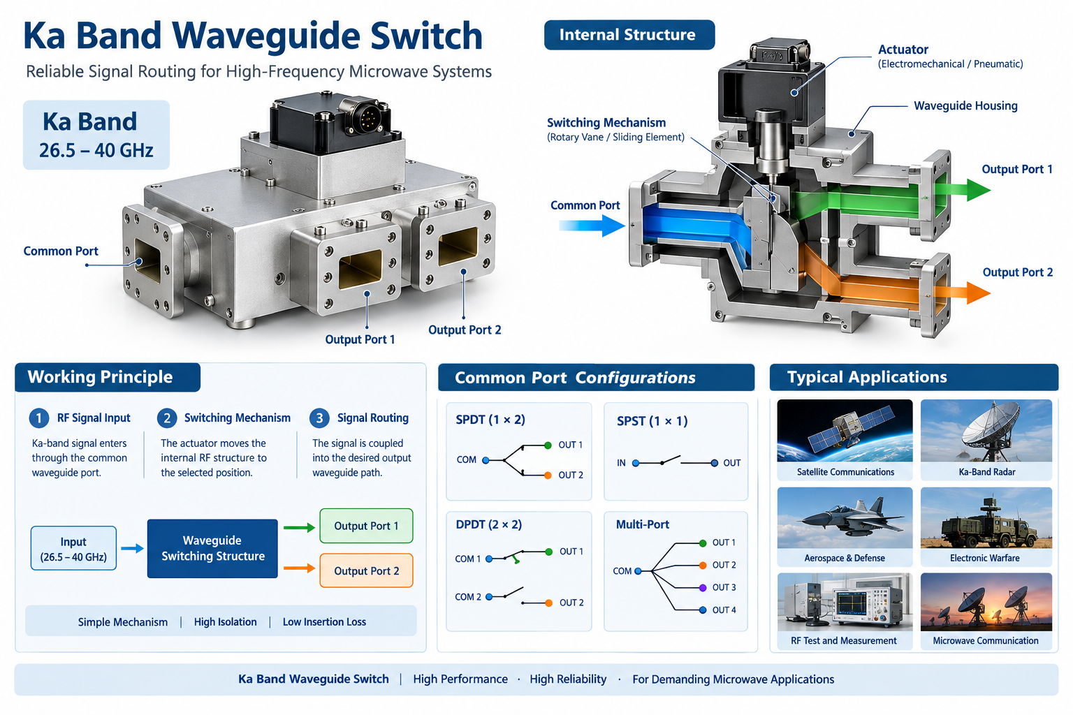
A Ka band waveguide switch is an electromechanical or electronically controlled microwave device used to change the transmission path of a Ka-band signal. Instead of carrying the RF signal through a coaxial conductor, the switch uses a metallic waveguide structure to guide electromagnetic energy.
The Ka band generally covers approximately 26.5 GHz to 40 GHz. Specific operating ranges depend on the waveguide standard, design architecture, and application requirements.
Key point: A Ka band waveguide switch is not simply a conventional RF switch operating at a higher frequency. Its mechanical dimensions, electromagnetic structure, mode control, manufacturing tolerances, surface finish, and interface design all become increasingly important as frequency increases.
A waveguide switch controls the propagation path of electromagnetic energy by mechanically or electronically changing the RF configuration inside the waveguide assembly.
The Ka-band microwave signal enters the switch through a waveguide port. The waveguide dimensions are selected according to the required frequency range and propagation mode, commonly the dominant TE mode.
An actuator moves an internal RF structure into a selected position. Depending on the switch architecture, this mechanism can connect one input to different output ports or disconnect specific signal paths.
When the switch reaches the selected position, the electromagnetic field is coupled into the desired waveguide path while unwanted paths are isolated.
The actuator may be controlled electrically, pneumatically, or through another control mechanism. Position sensors can provide feedback to verify that the RF switch has reached the required state.
At millimeter-wave frequencies, transmission-line losses, connector discontinuities, and parasitic effects become increasingly significant. Waveguides offer several advantages for high-frequency microwave signal routing.
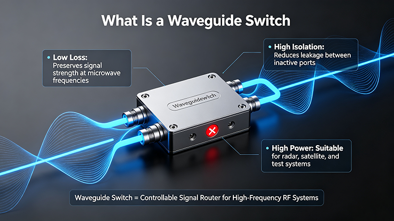
Properly designed waveguide structures can provide low RF transmission loss, helping preserve signal power across the switching path.
Waveguide switching structures can achieve strong isolation between selected and unselected ports, which is important in multi-channel microwave systems.
Waveguide switches can be suitable for applications where RF power levels exceed the practical capability of miniature coaxial switching structures.
Waveguide technology provides a controlled electromagnetic environment for demanding Ka-band applications.
An SPDT (Single Pole Double Throw) waveguide switch has one common RF port and two selectable output paths. It is frequently used to switch a signal between two antennas, loads, filters, or microwave subsystems.
An SPST (Single Pole Single Throw) switch provides a simple on/off RF path. It can be used to connect or disconnect a microwave signal within a test or communication system.
A DPDT (Double Pole Double Throw) configuration provides multiple switching paths and can be used in more complex microwave routing architectures.
Multi-port configurations allow a single microwave subsystem to select among several RF channels. They are useful for antenna selection, redundant transmit chains, receiver routing, and automated measurement systems.
When evaluating a Ka band waveguide switch, engineers should consider both RF and mechanical specifications.
| Specification | Why It Matters |
|---|---|
| Frequency Range | Defines the usable Ka-band operating range and determines compatibility with the microwave system. |
| Insertion Loss | Determines how much signal power is lost through the selected RF path. |
| Isolation | Indicates how effectively unwanted RF energy is blocked from inactive ports. |
| VSWR | Describes impedance matching and the magnitude of reflected RF power. |
| Power Handling | Determines the maximum RF power the switch can safely handle under specified conditions. |
| Switching Time | Defines how quickly the switch changes between RF states. |
| Actuator Type | Determines how the mechanical RF switching mechanism is operated. |
| Repeatability | Important for systems requiring consistent RF characteristics after repeated switching cycles. |
| Operating Life | Defines the expected number of switching cycles under specified operating conditions. |
| Waveguide Interface | Ensures mechanical and electromagnetic compatibility with other Ka-band components. |
Two of the most important RF parameters are insertion loss and isolation.
Insertion loss represents the reduction in RF power caused by inserting the switch into the transmission path. Lower insertion loss is generally desirable because it minimizes attenuation of the useful microwave signal.
At Ka-band frequencies, even small mechanical discontinuities or dimensional deviations can affect insertion loss. Therefore, precision manufacturing and electromagnetic optimization are important.
Isolation describes the attenuation between an active port and an inactive port. High isolation helps prevent unwanted signal leakage and crosstalk between microwave channels.
For systems containing multiple transmitters, receivers, antennas, or measurement channels, isolation can be especially important because leakage from an inactive path may affect system measurements or receiver performance.
VSWR (Voltage Standing Wave Ratio) is another critical parameter for Ka-band switching applications. Poor impedance matching can increase reflected power and reduce the efficiency of the RF chain.
A lower VSWR generally corresponds to better matching. Return loss provides another way to express the same reflection behavior, with higher return loss generally indicating lower reflected power.
Because Ka-band wavelengths are relatively short, small dimensional changes can have a measurable impact on impedance matching and RF performance.
Ka-band frequencies are widely used in modern satellite communication systems. Waveguide switches can route signals between redundant RF chains, antennas, filters, amplifiers, and test equipment.
Radar systems operating in the Ka band can use waveguide switches for signal routing, antenna selection, calibration, subsystem redundancy, and test configurations.
High-frequency microwave switching components can be integrated into aerospace and defense platforms where compact packaging, reliable operation, and controlled RF performance are required.
Microwave switching networks can be used to route signals among RF sources, receivers, antennas, and other subsystems in electronic warfare equipment.
Automated microwave test systems often use waveguide switches to connect a device under test to different measurement paths without manually changing cables or waveguide assemblies.
Ka-band point-to-point and specialized microwave communication systems can use waveguide switches for channel selection and system redundancy.
| Feature | Ka Band Waveguide Switch | Coaxial RF Switch |
|---|---|---|
| Transmission Structure | Metallic waveguide | Coaxial transmission line |
| High-Frequency Suitability | Excellent for many millimeter-wave applications | Depends strongly on connector and switch architecture |
| Power Handling | Can be high for appropriately designed waveguide systems | Varies significantly by design |
| Insertion Loss | Can be very low within its specified band | Depends on switch technology and frequency |
| Physical Size | Often larger than miniature coaxial switches | Can be more compact |
| Integration | Requires compatible waveguide interfaces | Convenient for coaxial RF systems |
The appropriate technology depends on the frequency, power level, available space, RF architecture, switching speed, environmental requirements, and interface requirements of the application.
Ka-band wavelengths are short, so manufacturing tolerances become increasingly important. Small dimensional errors can introduce impedance discontinuities and degrade RF performance.
The internal waveguide surface can affect conductor loss and RF performance. Appropriate material selection, plating, and surface treatment may therefore be required.
For electromechanical waveguide switches, the actuator must provide repeatable positioning over the expected operating life.
High RF power can generate heat within microwave components. Thermal design should consider both RF losses and the surrounding system environment.
Aerospace, satellite, radar, and defense applications may impose requirements for temperature cycling, vibration, shock, humidity, altitude, and other environmental conditions.
Ka band is commonly defined as approximately 26.5 to 40 GHz. Exact frequency allocations vary according to the application and industry standard.
It is used to route Ka-band microwave signals between different transmission paths. Common applications include satellite communications, radar, aerospace systems, electronic warfare equipment, and RF test systems.
Waveguide switches can provide strong RF performance at millimeter-wave frequencies and can offer low insertion loss, high isolation, and high power-handling capability when properly designed. The best choice depends on the complete system requirements.
Important specifications include frequency range, insertion loss, isolation, VSWR, power handling, switching time, switching life, actuator type, waveguide interface, environmental performance, and position indication.
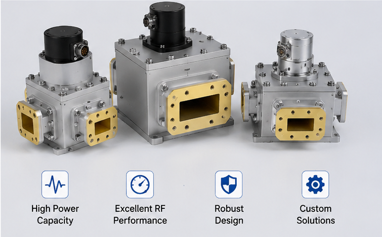
Depending on the manufacturer and application, customization may be available for frequency range, waveguide interface, port configuration, actuator, control electronics, mounting configuration, environmental requirements, and other mechanical or RF specifications.
Ka band waveguide switches are important components for routing high-frequency microwave signals in satellite communications, radar, aerospace, defense, electronic warfare, and RF test and measurement systems. Their waveguide-based architecture can provide low insertion loss, high isolation, reliable RF transmission, and suitable power handling for demanding Ka-band applications.
When selecting a Ka band waveguide switch, engineers should evaluate frequency range, insertion loss, isolation, VSWR, RF power, switching time, mechanical life, actuator configuration, waveguide interface, and environmental requirements together. A properly specified switch can improve the reliability and RF performance of the entire microwave signal-routing system.
For a Ka-band microwave switching solution, provide the required frequency range, waveguide interface, number of ports, insertion loss, isolation, VSWR, power level, switching time, control method, and environmental requirements. These specifications allow the appropriate waveguide switch configuration to be evaluated for your RF system.
High-tech Enterprise, Feifeng Talent
Chief Engineer Wang graduated with a master's degree in high-power microwave from the Institute of Electronics, University of Chinese Academy of Sciences.
View Full Profile