What are Normally Closed vs Normally Open Switch Contacts?
Quick Answer
A Normally Open (NO) contact allows no current when the switch is at rest; it closes only when actuated. A Normally Closed (NC) contact allows current when at rest; it opens only when actuated. Most switches — push-buttons, limit switches, relays, contactors — are available in both NC and NO versions, and many switches include changeover contacts that combine both.
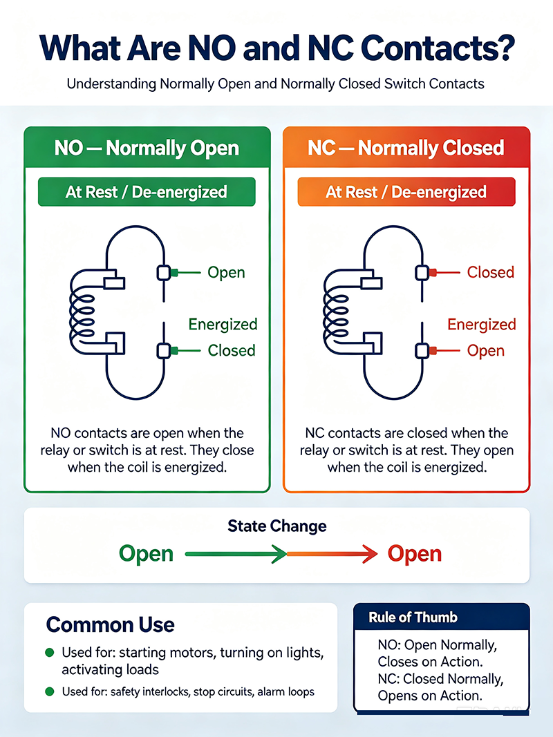
What Are NO and NC Contacts?
The terms describe the resting state of a switch — the position when no external force, button press, or electrical signal is applied.
- Normally Open (NO): contacts are separated when at rest. The circuit is broken until something actuates the switch.
- Normally Closed (NC): contacts are touching when at rest. Current flows until something actuates the switch to open the contacts.
A switch's default state is what it does when nothing is happening. Once actuated, the behavior reverses.
Schematic Symbols
NO and NC Contact Symbols
The NO symbol shows an open lever; the NC symbol shows a closed lever with a strike-through bar. Standard IEC 60617 symbols.
NO vs NC Comparison
Normally Open (NO)
- Open when at rest
- Closes when actuated
- Used for "turn on" actions
- Circuit default: OFF
- Common in start buttons, push-to-make
- Fail-safe: turns off when power is lost
Normally Closed (NC)
- Closed when at rest
- Opens when actuated
- Used for "stop" or "safety" actions
- Circuit default: ON
- Common in stop buttons, push-to-break
- Fail-safe: requires NC for emergency stops
Changeover (CO / SPDT) Contacts
A changeover or SPDT contact combines both: one common terminal, one NC terminal, and one NO terminal. Actuation moves the common from the NC contact to the NO contact. Changeover contacts are extremely common in relays and limit switches because they give the designer maximum flexibility.
Changeover Contact Symbol
Real-World Switch Examples
Push-Buttons
- NO push-button: press to close (start buttons, doorbells).
- NC push-button: press to open (stop buttons, emergency stops).
Limit Switches
- NO limit switch: closes when actuator reaches limit position (e.g., machine overtravel detection).
- NC limit switch: opens when limit reached (used in safety circuits).
Relays and Contactors
- Most relays have both NO and NC contacts, often combined as SPDT or DPDT.
- Motor contactors typically use large NO power contacts for switching the load.
- Safety relays use NC contacts for fault detection.
Door and Safety Switches
- Door interlock: NC contact that opens when the door is opened.
- Limit switch: NO contact that closes when the door reaches its end position.
Pressure and Temperature Switches
- NC: opens when threshold exceeded (overpressure or overtemperature trip).
- NO: closes when threshold reached (e.g., low-pressure alarm).
Failure Modes and Safety
The choice of NC or NO has critical implications for safety circuits.
Fail-Safe Design
In an emergency-stop or safety interlock, an NC contact is the standard choice. If the wire breaks or the contact fails open, the circuit trips and stops the machine. With an NO contact, a broken wire leaves the safety circuit unable to stop the machine — a dangerous condition.
Positive Opening
Safety contacts must be positively opening: the actuator physically pulls the contacts apart. A contact that relies on a spring alone may fail to open if the spring breaks or corrodes.
Where Each Is Used
| Application | Preferred Contact |
|---|---|
| Start button | NO |
| Stop button | NC |
| Emergency stop | NC |
| Door interlock | NC |
| Limit switch (detection) | NO |
| Limit switch (safety) | NC |
| Motor contactor | NO (power contacts) |
| Overpressure alarm | NC |
| Low-pressure alarm | NO |
| Push-to-test indicator | NO |
Mechanical vs Electronic Implementation
Mechanical Switch
Physical contacts; clearly open or closed. Mechanical NC/NO contacts can switch AC and DC.
Solid-State Relay
Transistor-based; NO by default (off until energized). Some have NC equivalents using depletion-mode devices.
Reed Switch
Magnetic actuation; typically SPST-NO or SPST-NC depending on contact arrangement.
Proximity Sensor
NO or NC versions available. NC sensors pass current when no target; NO passes current only when a target is detected.
Choosing Between NC and NO
- Determine the default state needed: ON or OFF.
- For safety-critical functions, prefer NC (fail-safe principle).
- For convenience functions (start, indicator), NO is standard.
- Consider system behavior on power loss.
- Match the contact rating to voltage and current.
- For complex logic, use changeover contacts to cover both states.
Common Mistakes
- Using NO for emergency stop: a broken wire cannot stop the machine.
- Confusing "normal" with "idle": "normal" means "unactuated," not "off" or "on."
- Mixing NC and NO logic in PLC programs without proper mapping: verify the I/O assignment matches the physical contact.
- Forgetting positive-opening requirement: spring-only NC contacts can fail to open.
- Underrating contact current: arcing destroys NC/NO contacts faster than expected.
Verification & Testing
- Use a multimeter in continuity mode to verify contact state at rest.
- Apply the actuator and recheck — NO should close, NC should open.
- Measure contact resistance under load (should be < 100 mΩ when new).
- Verify insulation resistance between contacts (> 100 MΩ).
- Test under rated voltage and current for the expected cycle count.
Key Takeaways
- NO contacts are open at rest; NC contacts are closed at rest.
- "Normal" means unactuated — not "off" or "on."
- NC is the standard for safety and emergency-stop circuits.
- Changeover (SPDT) contacts combine both for maximum flexibility.
- Always verify the default state matches the safety intent.
Frequently Asked Questions
What is the difference between NC and NO contacts?
NC (Normally Closed) contacts allow current flow at rest; NO (Normally Open) contacts block current at rest. Actuation reverses the state.
What does "normal" mean in NC and NO?
"Normal" means the unactuated, resting state. It does not imply "off" or "on" — it just describes the default position.
Which contact type should I use for emergency stop?
Always use NC contacts in emergency-stop circuits. If the wire breaks, the NC contact opens and stops the machine — fail-safe behavior.
Can a switch have both NC and NO contacts?
Yes. Changeover or SPDT switches have one common, one NC, and one NO terminal. Actuation moves the common between the two.
What is positive opening?
Positive opening is a mechanical design where the actuator physically forces the contacts apart, independent of any spring. Required for safety-certified NC contacts.
-
What is an RF transfer switch? Learn how RF transfer switches work, the main types (coaxial, waveguide, latching), key specifications, and how they are used in redundancy, ATE, and broadcast systems.Sep 07 ,26
-
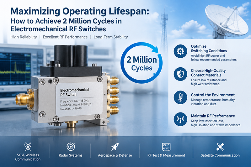
How to extend the operating lifespan of electromechanical RF switches. Practical guidance on cold switching, derating, contact wear, environment, and maintenance for coaxial and waveguide RF switches.Sep 07 ,26
-
What is a rotary switch? Learn how a rotary switch works, its main types, key specifications, and the most common applications in industrial controls, audio, automotive, and test equipment.Sep 01 ,26
-
Every RF switch has a finite life cycle. Whether it is a coaxial electromechanical relay, a PIN-diode solid-state switch, or an MEMS device, un...Aug 29 ,26
-
A beginner's guide to switches — learn what an electrical switch is, the different switch types (mechanical, toggle, push-button, rotary, slide, limit, reed), how they work, and how to choose the right one for your project.Aug 29 ,26
-
Selecting the appropriate RF signal routing hardware is critical to optimizing performance, maintaining signal integrity, and minimizing insertion loss in modern RF and microwave systems.Aug 26 ,26
-
Hot switching is an important concept in RF engineering, microwave systems, electronics, power systems, and automated test equipment. Understanding what hot switching is, how it works, and why it matters can help engineers select the right RF switch and avoid performance degradation or premature component failure.Aug 24 ,26
-
A comprehensive guide to DPDT switches, their internal mechanics, wiring configurations, operating principles, applications, and selection criteria.Aug 24 ,26
-
The main difference between SPST and DPDT switches is their number of poles and throws. The pole represents the number of independent circuits being controlled, while the throw represents the number of selectable connections for each pole.Aug 18 ,26
About the Author — MeiXun Team
Chief Engineer Wang
High-tech Enterprise, Feifeng Talent
Chief Engineer Wang graduated with a master's degree in high-power microwave from the Institute of Electronics, University of Chinese Academy of Sciences.
View Full Profile- RF Switch Circuit Diagram
- RF Switch
- Ohm's Law
- dBm to Watt
- mW to dBm
- Wavelength to Frequency
- RF Connector
- SMA Connector
- RF Switch Module
- RF Coupler
- RF PIN Switch
- Microwave Coaxial Switch
- PIN Switch
- Coaxial RF Switch
- Waveguide Switch
- Microwave Switch
- Low Noise Amplifier
- PIN Diode Switch
- Coaxial Switch
- RF Microwave Switch
- SPST Switch