SPDT vs DPDT Coaxial Switches: A Complete Selection Guide

Choosing between an SPDT and a DPDT coaxial switch is one of the most common design decisions RF engineers face. The wrong choice can mean higher cost, larger board area, or compromised signal integrity. This guide breaks down the technical differences, typical applications, and a clear decision framework so you can select the right switch with confidence.

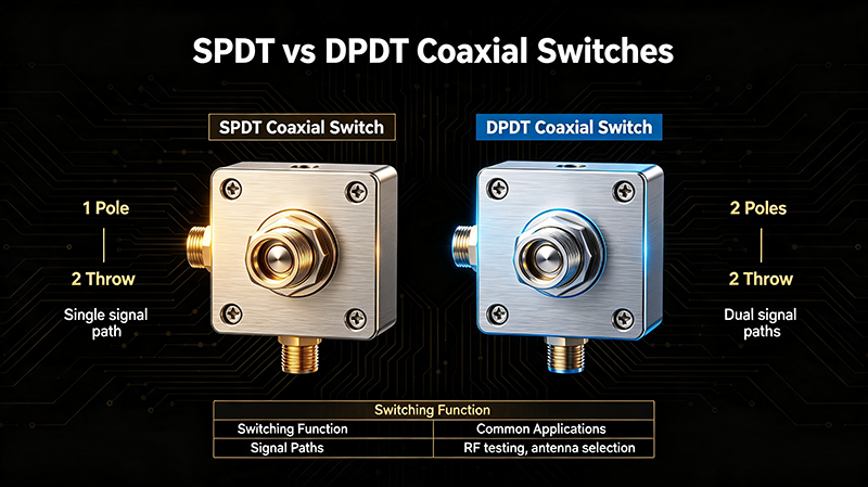
SPDT vs DPDT Coaxial Switches

1. Switch Topologies Explained

1.1 What is an SPDT Switch?

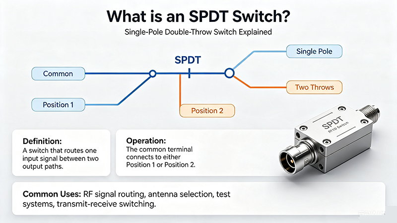
What is an SPDT Switch

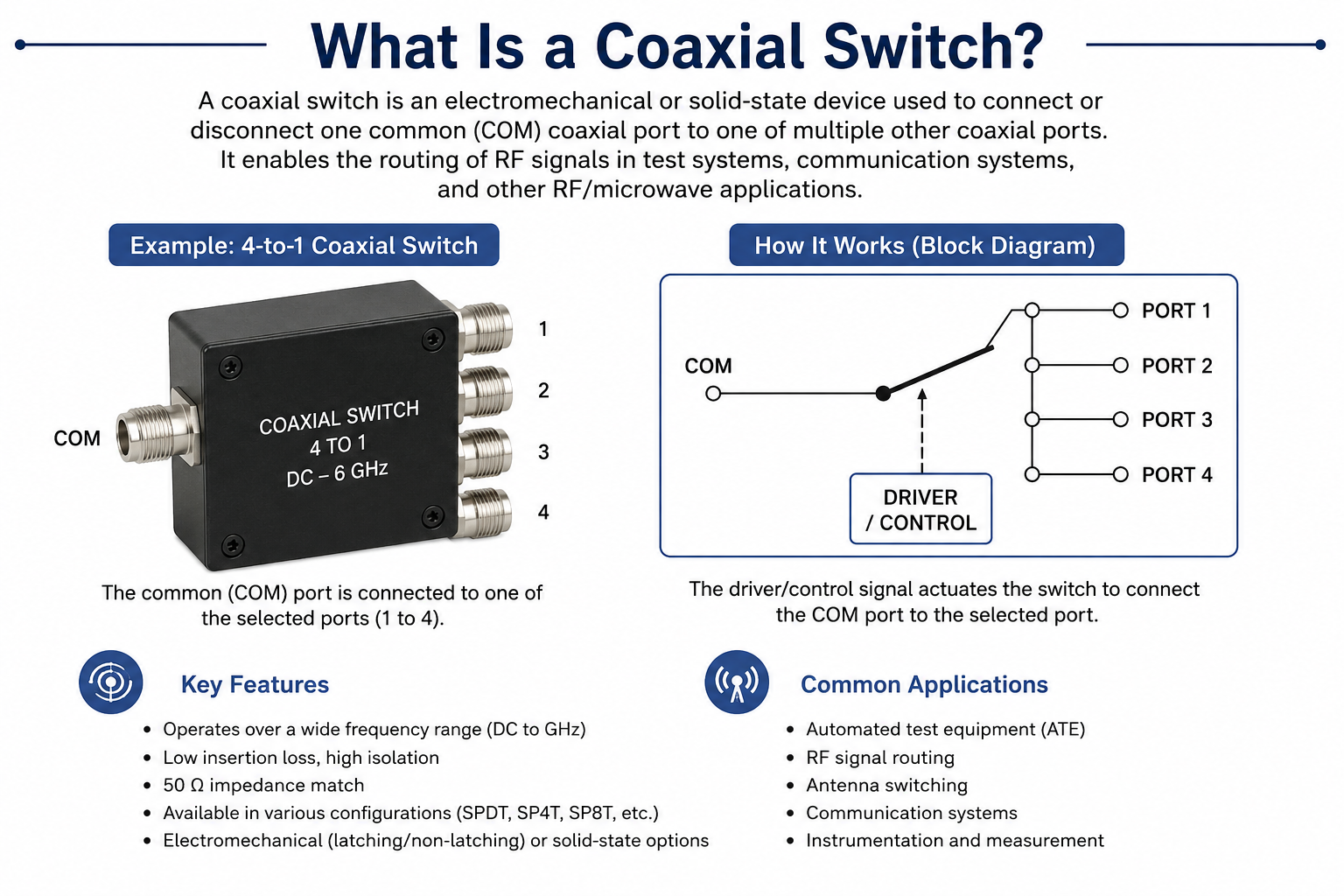
SPDT stands for Single-Pole Double-Throw. It has one input port and two output ports. The RF signal is routed to either output A or output B, never both simultaneously. It is the most common RF switch topology, used when you need to choose between two signal paths.
1.2 What is a DPDT Switch?

What is a DPDT Switch

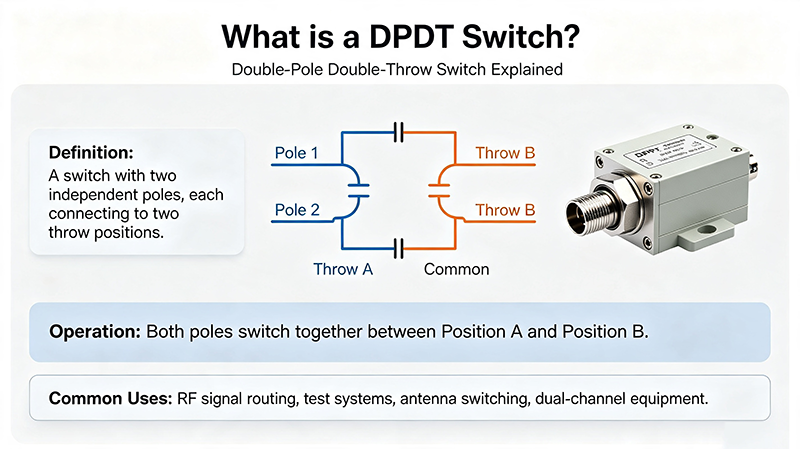
DPDT stands for Double-Pole Double-Throw. It contains two independent SPDT switches mechanically or electrically ganged together, sharing a common control line. Each pole switches between two throws, making DPDT ideal for signal reversal, differential routing, or simultaneous dual-path control.

1.3 Visual Topology Comparison

  • SPDT: 1 input → 2 outputs (A or B)
  • DPDT: 2 inputs → 2 outputs each (A1/B1 and A2/B2, switched together)

2. Key Specifications Compared

Parameter SPDT DPDT
Port count 3 ports (1 input, 2 output) 6 ports (2 inputs, 4 outputs)
Switching function Select between 2 paths Two paths switched simultaneously
Typical isolation 60–90 dB (EM) 60–85 dB (EM)
Insertion loss 0.2–0.5 dB @ 6 GHz 0.3–0.7 dB @ 6 GHz
Switching speed 10–25 ms (EM), <1 µs (solid-state) 15–30 ms (EM), <1 µs (solid-state)
Cycle life 5–10 million cycles 2–5 million cycles
Cost Lower Higher (~1.8× to 2.5×)
PCB footprint Smaller Larger
Control complexity 1 driver line 1 driver line (ganged) or 2 independent
Engineering Note: DPDT switches typically have slightly higher insertion loss because the signal passes through two pole paths in series. Always budget 0.1–0.2 dB extra loss budget for DPDT designs.

3. SPDT Coaxial Switch Deep Dive

3.1 Internal Structure

An SPDT coaxial switch contains a single latching relay or solid-state switch network. The RF trace is routed via a movable contact (EM) or PIN-diode bridge (solid-state). High-end models use self-terminating designs where the unused port is automatically terminated with 50 Ω to prevent reflections.

3.2 Strengths

  • Lowest insertion loss per dollar
  • Compact footprint — ideal for dense ATE racks
  • Wide variety of connector options (SMA, N-Type, TNC, BNC)
  • Excellent isolation, especially in fail-safe latching designs

3.3 Limitations

  • Cannot reverse signal direction by itself
  • Requires two SPDTs to replicate basic DPDT function
  • Single point of failure for two paths

4. DPDT Coaxial Switch Deep Dive

3.1 Internal Structure

A DPDT coaxial switch essentially integrates two SPDT switches on a common mechanical frame with a shared actuator. Both poles toggle in unison, providing synchronized switching of two independent signal paths.

4.2 Strengths

  • Reverses signal direction with a single control line
  • Saves PCB space compared to two discrete SPDTs
  • Synchronized switching eliminates timing skew between paths
  • Common in transmit/receive (T/R) duplexing and antenna swapping

4.3 Limitations

  • Higher cost and larger size
  • Slightly higher insertion loss
  • Reduced cycle life due to dual-contact wear
  • More complex replacement if one pole fails

5. Typical Applications

5.1 When to Choose SPDT

  • Selecting between two antennas
  • Routing to a redundant instrument
  • Switching between DUT and bypass path in ATE
  • Band-select filtering in multi-band radios
  • Simple source/load selection in production test

5.2 When to Choose DPDT

  • Transmit/Receive (T/R) switching in radar and radios
  • Reversing signal flow direction in a test loop
  • Differential signal routing (e.g., balanced pair switching)
  • Dual-channel redundancy with simultaneous transfer
  • Cross-connect switching in matrix networks

6. Selection Decision Tree

  1. Do you need to switch one path or two? One path → SPDT. Two synchronized paths → DPDT.
  2. Is signal reversal required? Yes → DPDT. No → SPDT.
  3. Is PCB space critical? Yes → SPDT, or DPDT if two paths are mandatory.
  4. Is cost the dominant constraint? Yes → SPDT.
  5. Do you need independent control of two paths? Yes → two SPDTs (not ganged DPDT).
  6. Does your frequency exceed 18 GHz? Verify both topologies are available in your connector type.
Rule of Thumb: Use SPDT by default. Upgrade to DPDT only when you need synchronized dual-path switching or signal reversal that would otherwise require two SPDTs.

7. Common Pitfalls to Avoid

  • Ignoring termination: The unused SPDT port can reflect energy if not self-terminating or externally terminated with 50 Ω.
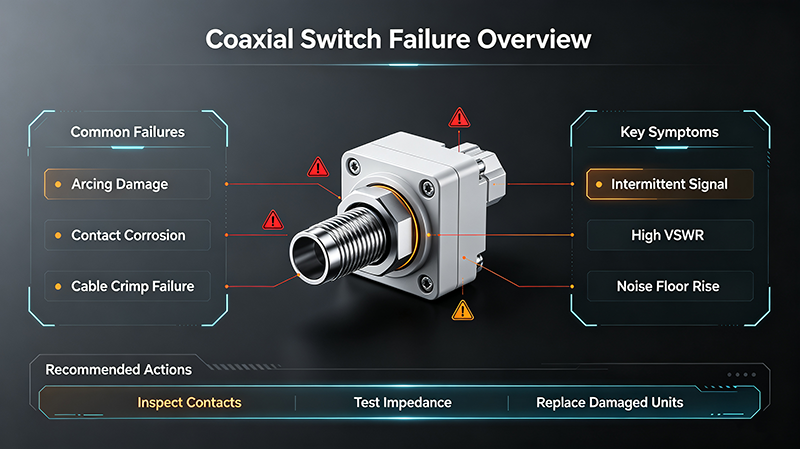
  • Hot-switching: Toggling under RF power welds contacts. Always sequence the system to remove RF power before switching.
  • Mismatched connector types: Mixing SMA and Type-N causes mechanical stress and VSWR spikes.
  • Underrated voltage: Ensure the driver board can source the latching current specified by the switch.
  • Over-torque on connectors: Use a calibrated torque wrench (8 in-lbs for SMA, 12 in-lbs for Type-N).
  • Ignoring cycle life: EM switches wear out. Track cycle count and plan replacement before failure.

8. Frequently Asked Questions

Q1: Can a DPDT switch be used as two independent SPDT switches?

Only if the switch supports independent pole control. A ganged DPDT toggles both poles simultaneously, which is not always equivalent to two independent SPDTs.

Q2: Is DPDT always more expensive than SPDT?

Generally yes — typically 1.8× to 2.5× the cost due to the dual mechanical structure. However, one DPDT can replace two SPDTs, reducing wiring, control complexity, and total system cost.

Q3: Which is better for high-isolation requirements?

Electromechanical SPDT and DPDT both deliver >80 dB isolation at low GHz. Solid-state versions of either are limited to 40–60 dB.

Q4: Do SPDT and DPDT switches come in solid-state versions?

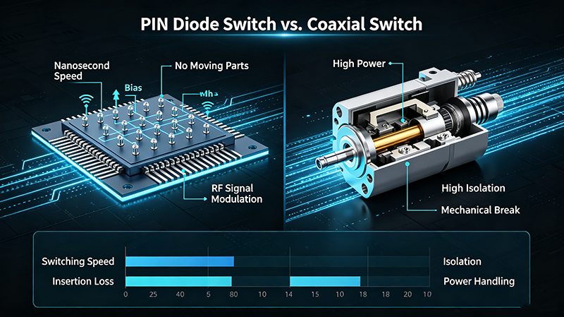
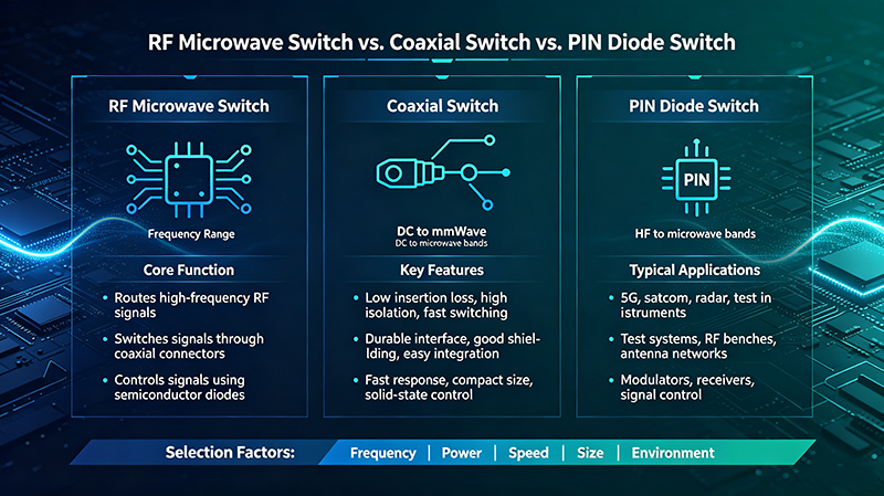
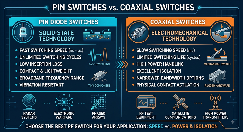
Yes. PIN-diode and GaAs-FET SPDT/DPDT switches are widely used where microsecond switching and infinite cycle life are required.

Q5: How do I decide between fail-safe and latching SPDT?

Fail-safe returns to a default position when power is removed — ideal for safety-critical systems. Latching holds its last state with no continuous power draw — better for power-sensitive or remote installations.

9. Conclusion

The choice between SPDT and DPDT coaxial switches comes down to the number of paths you need to switch and whether synchronized dual-path control or signal reversal is required. SPDT remains the workhorse for single-path selection, while DPDT excels in T/R duplexing, signal reversal, and differential routing. By following the decision tree and avoiding common pitfalls, you can select a switch that delivers optimal performance, reliability, and cost efficiency for your RF system.

Need Help Selecting the Right RF Switch?

Our engineers can help you choose between SPDT, DPDT, SPnT, and custom configurations.

Talk to an RF Engineer
About the Author — MeiXun Team

Wang

Chief Engineer Wang

High-tech Enterprise, Feifeng Talent

Chief Engineer Wang graduated with a master's degree in high-power microwave from the Institute of Electronics, University of Chinese Academy of Sciences.

View Full Profile
Wang

Chief Engineer Wang

High-tech Enterprise, Feifeng Talent

Chief Engineer Wang graduated with a master's degree in high-power microwave from the Institute of Electronics, University of Chinese Academy of Sciences.

In the same year, he joined CETC 40/41 for work and study. He has been committed to the design and development of microwave switches for a long time.

He has applied for 27 patents as the first inventor in the microwave switch field, with 6 authorized invention patents and 14 utility model patents.

The products he developed cover various application platforms such as civilian testing, vehicle-mounted, shipborne, airborne, and missile-borne.

RF Microwave Switch RF Switch Coaxial Switch PIN Diode Switch Low Noise Amplifier Waveguide Switch PIN Switch Microwave Switch