Selecting the right RF switch for your application requires understanding the fundamental differences between switch technologies. This comprehensive guide compares RF microwave switches, coaxial switches, and PIN diode switches, helping engineers and designers make informed decisions based on performance requirements, frequency ranges, and operational needs.
What is an RF Switch?
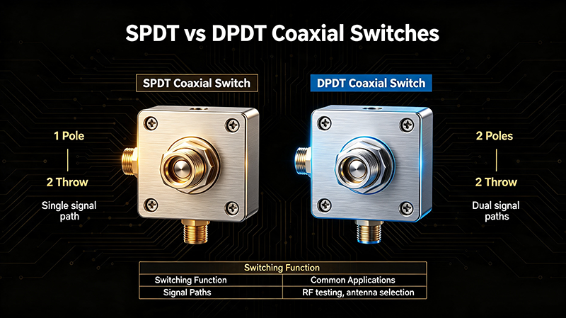
An RF switch is a device that controls the routing of radio frequency signals in a circuit. It functions as a single-pole double-throw (SPDT) or multi-throw switch, directing signals between different paths without significantly degrading signal quality. RF switches are essential components in communication systems, test equipment, radar systems, and many other applications requiring signal routing capabilities.
RF switches can be categorized by their switching technology, physical construction, frequency range, and performance characteristics. The three main types discussed in this guide—RF microwave switches, coaxial switches, and PIN diode switches—each offer distinct advantages for specific applications.
RF Microwave Switch
Overview
What It Is
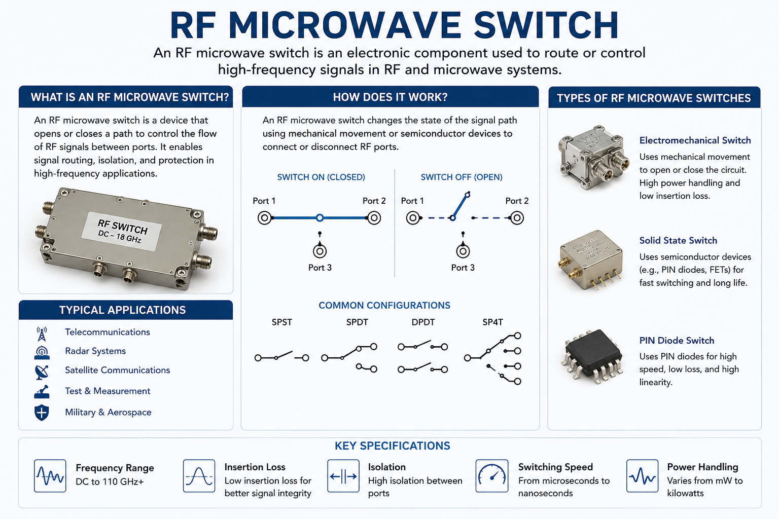
RF microwave switches are broad-category devices designed to operate at microwave frequencies, typically from 300 MHz to 300 GHz. They encompass various switching technologies including electromechanical, solid-state, and hybrid designs.
Key Characteristics
- Frequency range: 300 MHz to 300 GHz
- High frequency performance
- Multiple configurations
- Various technologies
Working Principle
RF microwave switches operate by physically or electronically connecting signal paths. Electromechanical microwave switches use electromagnetic coils to move physical contacts, while solid-state microwave switches use semiconductor devices to redirect signals without moving parts.
Types of Microwave Switches
Electromechanical
Uses relays with physical contacts moved by electromagnets. Offers excellent isolation and high power handling but with slower switching speeds and mechanical wear considerations.
Solid-State
Uses semiconductors (FETs, PIN diodes) for signal switching. Provides ultra-fast switching, long life, and silent operation but with limited power handling compared to electromechanical.
Optical
Uses optical control signals to switch RF paths. Offers excellent isolation and EMI immunity but with higher cost and complexity.
RF MEMS
Micro-electromechanical systems using tiny switches fabricated on semiconductor substrates. Combines solid-state reliability with performance approaching electromechanical devices.
Advantages of RF Microwave Switches
- Broad frequency coverage from UHF to mmWave
- High isolation options available
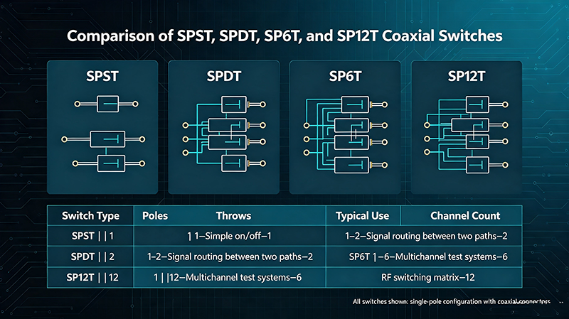
- Configurable as SPDT, SP4T, SP6T, and beyond
- Solutions available for virtually any application requirement
- Both absorptive and reflective configurations
Coaxial Switch
Overview
What It Is
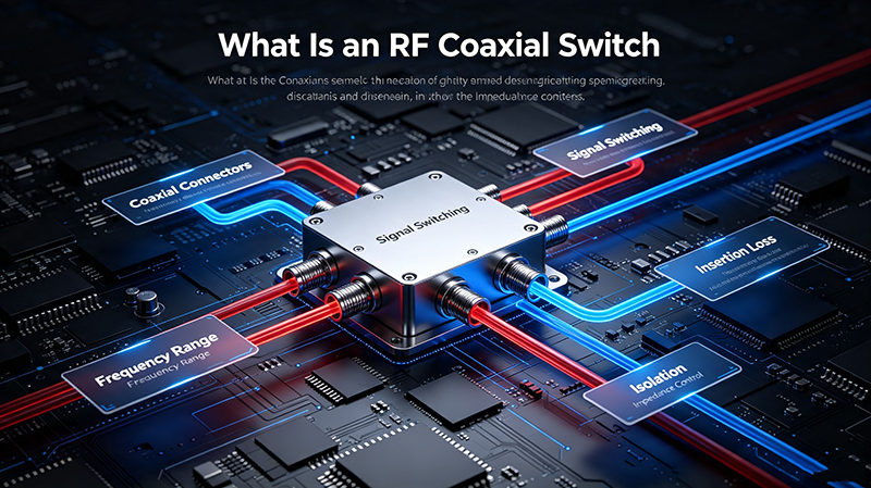
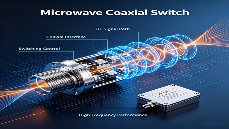
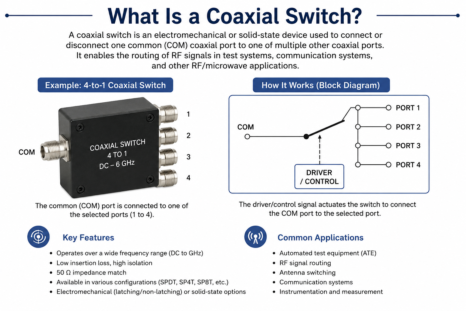
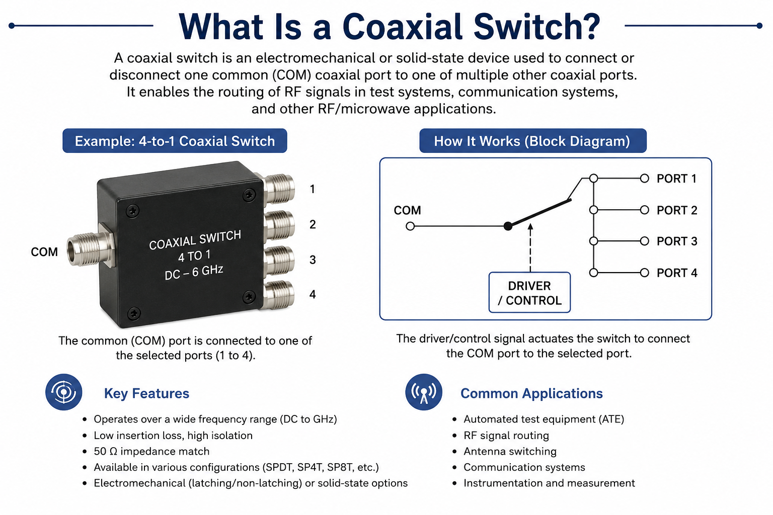
Coaxial switches are specifically designed with coaxial connector interfaces (N, SMA, BNC, etc.) for easy integration into coaxial transmission systems. They are typically electromechanical switches optimized for RF and microwave frequencies.
Key Characteristics
- Coaxial connector interfaces
- Excellent RF performance
- High power handling
- Typically electromechanical
Working Principle
Coaxial switches use a sliding or rotating contact mechanism housed in a coaxial structure that maintains consistent 50-ohm impedance throughout the switch. The electromagnetic actuator moves the center conductor and RF contacts between positions, ensuring minimal signal disruption during switching.
Connector Types
Coaxial switches are available with various connector interfaces, each suited for different frequency ranges and applications:
- SMA Connectors: Up to 27 GHz, compact size, common in lab and production
- N-Type Connectors: Up to 18 GHz, robust, higher power handling
- BNC Connectors: Up to 4 GHz, quick-connect, cost-effective
- Type F Connectors: Up to 3 GHz, CATV and video applications
- 2.92mm/K Connectors: Up to 40 GHz, precision applications
- 2.4mm Connectors: Up to 50 GHz, high-frequency precision
- 1.85mm/V Connectors: Up to 67 GHz, mmWave applications
Advantages of Coaxial Switches
- Excellent return loss and insertion loss characteristics
- High power handling capability (up to 100W+ CW)
- Superior isolation (60-80 dB typical)
- Standardized connector interfaces simplify integration
- Wide frequency coverage with appropriate connector types
- Well-suited for test and measurement applications
PIN Diode Switch
Overview
What It Is
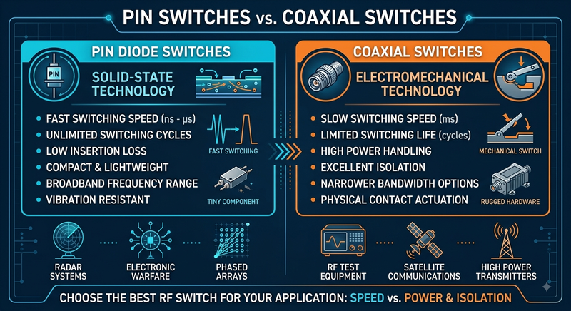
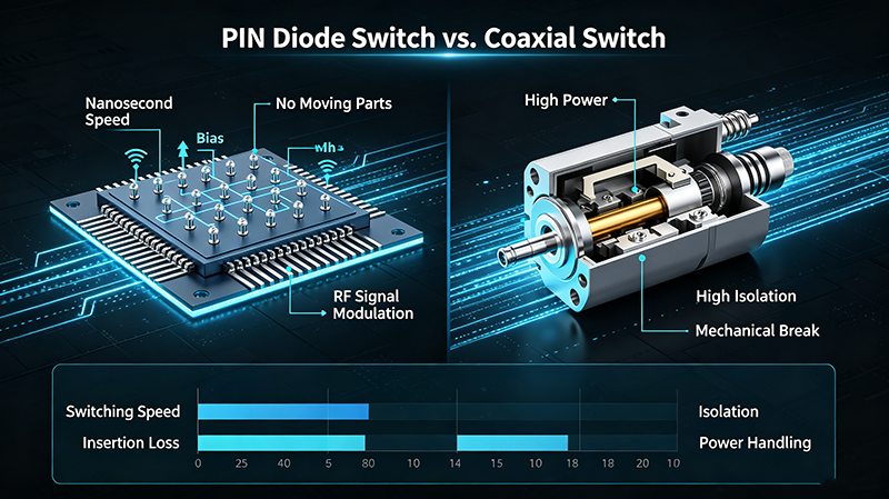
PIN diode switches are solid-state switches that use PIN diodes as switching elements. A PIN diode has an intrinsic semiconductor region between P-type and N-type regions, giving it unique RF switching characteristics.
Key Characteristics
- Solid-state operation
- Fast switching speed
- High reliability
- Low distortion
Working Principle
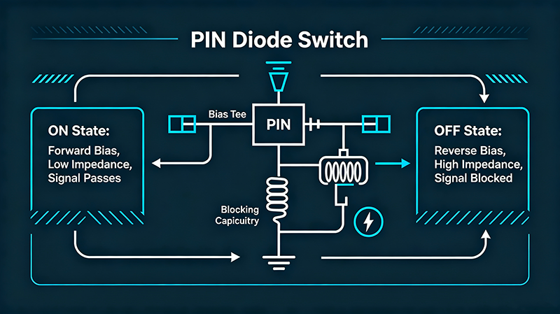
When a PIN diode is forward-biased, the intrinsic region fills with carriers, creating a low resistance path that allows RF signals to pass. When reverse-biased, the intrinsic region is depleted, creating a high impedance that blocks RF signals. This behavior makes PIN diodes ideal for RF switching applications.
Switch Configurations
Series Configuration
PIN diode placed in series with the signal path. Forward bias closes the circuit, reverse bias opens it. Simple design but isolation limited by diode capacitance.
Shunt Configuration
PIN diode connected to ground in shunt arrangement. Forward bias grounds the signal path, reverse bias allows signal through. Better isolation at high frequencies.
Bridge Configuration
Uses multiple PIN diodes in a bridge arrangement for improved isolation and balanced operation. Common in high-performance switches.
Hybrid Configuration
Combines series and shunt diodes for optimal performance across frequency range. Achieves both low insertion loss and high isolation.
Advantages of PIN Diode Switches
- Switching speed: nanoseconds to microseconds
- No mechanical wear or moving parts
- Virtually unlimited switching cycles
- Silent operation (no clicking)
- Compact size, suitable for integrated circuits
- Excellent linearity and low intermodulation distortion
- Low power consumption in standby
Direct Comparison: RF Microwave vs Coaxial vs PIN Diode Switches
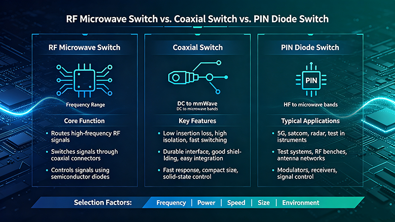
| Parameter | RF Microwave Switch | Coaxial Switch | PIN Diode Switch |
|---|---|---|---|
| Frequency Range | DC to 300+ GHz | DC to 67 GHz | 100 MHz to 50 GHz |
| Typical Technology | EM or Solid-State | Electromechanical | Solid-State (PIN Diode) |
| Switching Speed |
0.5 ms to 10 ms (EM) 1 ns to 1 us (SS) |
3 ms to 15 ms | 1 ns to 1 us |
| Insertion Loss | 0.3 dB to 2 dB | 0.2 dB to 1.5 dB | 0.5 dB to 2.5 dB |
| Isolation | 30 dB to 80 dB | 50 dB to 90 dB | 20 dB to 50 dB |
| Power Handling | 1W to 1000W CW | 10W to 500W CW | 0.1W to 50W CW |
| Lifetime (Cycles) | 10^6 to 10^10 | 10^6 to 10^7 | 10^10+ |
| Operating Temperature | -55C to +125C | -40C to +85C | -65C to +150C |
| Size | Medium to Large | Medium | Compact to Miniature |
| Cost Range | $50 to $5000+ | $100 to $3000 | $5 to $500 |
| Typical Applications | Radar, Satcom, Test | Test Equip, Labs | Wireless, Mobile, IoT |
Application Suitability
| Application | RF Microwave | Coaxial | PIN Diode |
|---|---|---|---|
| 5G Infrastructure | |||
| Test & Measurement | |||
| Military Radar | |||
| Satellite Comm | |||
| Smartphone Front-End | |||
| IoT Devices | |||
| Medical Equipment | |||
| Automotive Radar | |||
| Production Test | |||
| Laboratory R&D |
How to Choose the Right Switch
Selection Decision Flow
Define Frequency Requirements
Determine your operating frequency range. If above 40 GHz, prioritize specialized microwave switches. For DC to 40 GHz, all types are viable.
Evaluate Switching Speed Needs
Need sub-microsecond switching? Choose PIN diode or solid-state microwave switches. Millisecond switching is acceptable? Electromechanical (coaxial or microwave) offer better isolation and power handling.
Assess Power Requirements
High power (>10W)? Use electromechanical coaxial or microwave switches. Low power (<1W)? PIN diode or solid-state are ideal for size and integration benefits.
Consider Isolation Needs
Require >50 dB isolation? Electromechanical switches excel. Can tolerate 20-40 dB? PIN diode offers speed and reliability advantages.
Review Environmental Requirements
Extreme temperatures or vibration? Solid-state (PIN diode) has no moving parts. Standard environments? All types perform well.
Calculate Lifecycle Costs
Consider both unit cost and expected switching cycles. High-cycle applications favor solid-state. Low-cycle, high-power favors electromechanical.
Quick Reference Guide
Choose RF Microwave Switch When:
You need broad frequency coverage, specialized configurations, or high-frequency mmWave performance. Microwave switches offer the widest technology choices and performance options.
Choose Coaxial Switch When:
You need easy connector integration, high power handling, and excellent isolation. Coaxial switches are ideal for test equipment, labs, and applications requiring frequent connector changes.
Choose PIN Diode Switch When:
You need fast switching, long life, compact size, and integration into circuits. PIN diode switches excel in mobile devices, wireless infrastructure, and high-cycle applications.
Consider All Three When:
Your application spans 1-10 GHz with moderate requirements. Evaluate trade-offs between speed, power, isolation, and cost to find the optimal solution.
Frequently Asked Questions
Conclusion
Understanding the differences between RF microwave switches, coaxial switches, and PIN diode switches is essential for selecting the right component for your application. Each switch type offers distinct advantages: RF microwave switches provide the broadest frequency coverage and technology options, coaxial switches excel in test and measurement with superior connector integration, and PIN diode switches offer unmatched speed and reliability for high-cycle applications.
The optimal choice depends on your specific requirements including frequency range, switching speed, power handling, isolation needs, environmental conditions, and lifecycle expectations. Use the comparison tables, selection flowcharts, and application guidance in this article to narrow down your options, and consult with switch manufacturers or distributors when your requirements are particularly demanding or unique.
For most applications, the decision framework of defining frequency requirements, evaluating switching speed needs, assessing power requirements, and considering isolation and environmental factors will guide you to the most appropriate switch technology for your design.
Need Help Selecting the Right RF Switch?
Our technical team can help you choose the optimal switch solution based on your specific application requirements and performance specifications.
Contact Our Technical Team