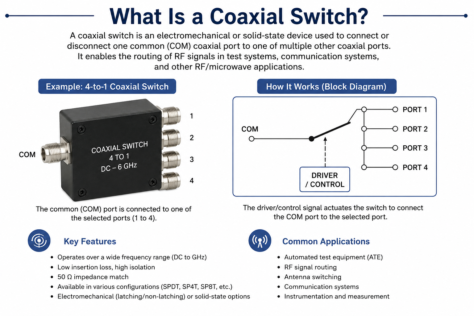
Specifying a coaxial switch requires careful evaluation of multiple technical parameters that directly impact system performance. Whether designing test equipment, communication systems, or defense applications, understanding these five critical specifications ensures optimal switch selection and reliable system operation.
Frequency Range
The frequency range defines the minimum and maximum signal frequencies that the coaxial switch can handle while maintaining acceptable performance. This parameter determines whether the switch is suitable for your specific application band.
What to Look For
- Verify VSWR and insertion loss specifications across the entire operating range
- Check if specs are flat or vary significantly across frequency
- Ensure connectors match your frequency requirements
- Consider frequency range when planning future system upgrades
Frequency Range = f_max / f_min (Bandwidth Ratio)
Connector-Frequency Matching
SMA connectors support DC to 27 GHz typically. For higher frequencies, consider 2.92mm (40 GHz), 2.4mm (50 GHz), or 1.85mm (67 GHz) precision connectors. Mismatched connectors can significantly degrade performance.
Isolation
Isolation measures how effectively the switch prevents signals from coupling between the input and output ports when in the off state. High isolation is critical for preventing signal interference and maintaining system sensitivity in receiver applications.
Why Isolation Matters
- Prevents transmitter signals from bleeding into sensitive receivers
- Reduces intermodulation and spurious responses
- Critical for multi-channel systems and signal routing
- Higher isolation enables systems with greater dynamic range
Isolation (dB) = 10 x log10(P_input / P_leakage)
Insertion Loss
Insertion loss represents the amount of signal power lost when passing through the switch in its on state. Lower insertion loss means less signal degradation and better system efficiency. This parameter is especially critical in loss-sensitive systems.
Impact on System Design
- Directly affects system noise figure (NF increase = insertion loss)
- Reduces effective transmit power
- Cumulative in cascaded systems
- More critical at higher frequencies
NF_total (dB) = IL_switch + NF_subsequent
Real-World Example
In a receiver with 0.5 dB switch insertion loss, if the subsequent amplifier has 2 dB noise figure, the total system noise figure becomes 2.5 dB—the switch adds 0.5 dB directly to the system noise figure.
Power Handling
Power handling capability defines the maximum RF power the switch can accommodate without damage or performance degradation. This parameter must exceed your system's peak and average power requirements with appropriate margin.
Power Rating Types
- CW (Continuous Wave) Rating: Sustained power handling under steady-state conditions
- Peak Power Rating: Maximum instantaneous power during pulsed operation
- Hot Switching Rating: Power handled while switching—typically much lower
- Through Path vs Terminated: Different ratings for active vs isolated paths
P_derated = P_max x (1 - |Gamma|^2) / (1 - S^2) where S = worst-case VSWR
Application Power Requirements
Test equipment: 1-10W typically. Commercial transmitters: 10-100W. High-power radar and broadcast: 100W to multiple kW. Match switch ratings to your specific application power levels with at least 3:1 safety margin.
Switching Speed
Switching speed encompasses the time required for the switch to change states and for signals to stabilize after switching. This parameter is critical for time-sensitive applications, frequency hopping systems, and automated test equipment.
Speed Specifications Explained
- Operate Time: Time from command to initial contact movement
- Release Time: Time to return to default position
- Setting Time: Time for signals to settle within specifications
- Cycle Time: Minimum time between consecutive operations
Total System Settling Time
The switch operate time is just part of the equation. Include time for RF settling (often 10-50 ms for connectors to stabilize), control system latency, and any interlock verification when calculating total switching time.
Coaxial Switch Specification Checklist
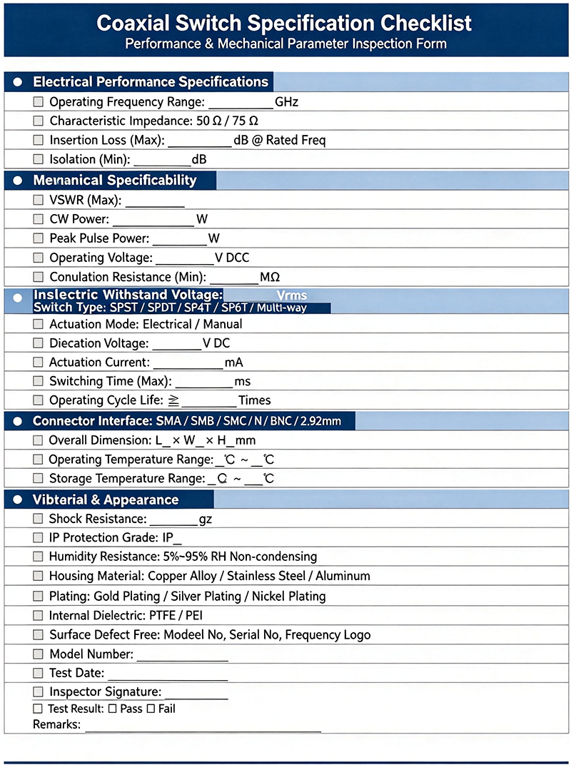
Confirm full-range performance, not just rated frequency
Verify worst-case isolation across frequency range
Calculate impact on system noise figure and budget
Lower VSWR means better impedance match
Include VSWR derating in calculations
Verify ratings if switching under power
Include settle time in system timing budget
Confirm compatibility with control system
Verify specs across full temperature range
Ensure MTBF meets application requirements
Frequently Asked Questions
Conclusion
Selecting the right coaxial switch requires balancing five critical parameters: frequency range, isolation, insertion loss, power handling, and switching speed. Each parameter directly impacts system performance, and trade-offs are often necessary when optimizing for specific applications.
Always review complete datasheets rather than relying solely on summary specifications. Pay attention to how parameters vary across frequency and temperature, and verify that drive requirements match your control system capabilities. Including appropriate safety margins for power handling and reviewing isolation curves across your operating band prevents field failures and performance issues.
Whether specifying switches for test equipment, communication infrastructure, or defense systems, the principles outlined in this guide provide a framework for making informed decisions that balance performance requirements against cost and availability constraints.
Need Help Specifying a Coaxial Switch?
Our technical team can help you select the optimal coaxial switch based on your specific system requirements and performance parameters.
Contact Our Technical Team