Low Noise Amplifier (LNA): Complete Guide to RF Low-Noise Amplifiers

Master every aspect of LNAs: technical principles, application scenarios, selection strategy, and commercial sourcing.

Overview

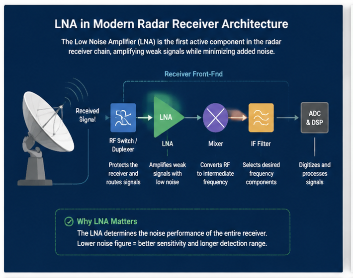
A Low Noise Amplifier (LNA) is the cornerstone of every modern RF receiver. Positioned directly after the antenna, it amplifies extremely weak signals while contributing minimal additional noise, thereby setting the overall sensitivity, dynamic range, and link budget of the entire system. From 5G base stations and phased-array radar to GNSS modules and software-defined radios, no high-performance wireless system can function without a well-designed LNA at its front end.

This guide organizes the entire LNA knowledge base into four focused clusters: technical fundamentals, application scenarios, selection criteria, and commercial sourcing. Whether you are an RF engineer, system architect, or procurement specialist, the following sections provide the insights you need to specify, design, and source the right LNA for your application.

Technical Cluster

Fundamentals

What Is a Low Noise Amplifier?

What Is a Low Noise Amplifier

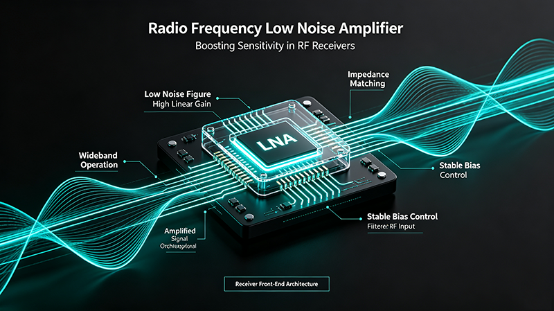
A Low Noise Amplifier is a specialized RF amplifier engineered to add the smallest possible amount of noise while boosting the amplitude of weak signals captured by an antenna. It is typically the first active stage in a receiver chain, so its noise figure directly determines the system noise floor as described by Friis' formula. LNAs are built using transistors such as GaAs pHEMT, GaN HEMT, SiGe HBT, or RF CMOS, each chosen for the application's frequency band, power budget, and integration requirements.

How Does an LNA Work?

How Does an LNA Work

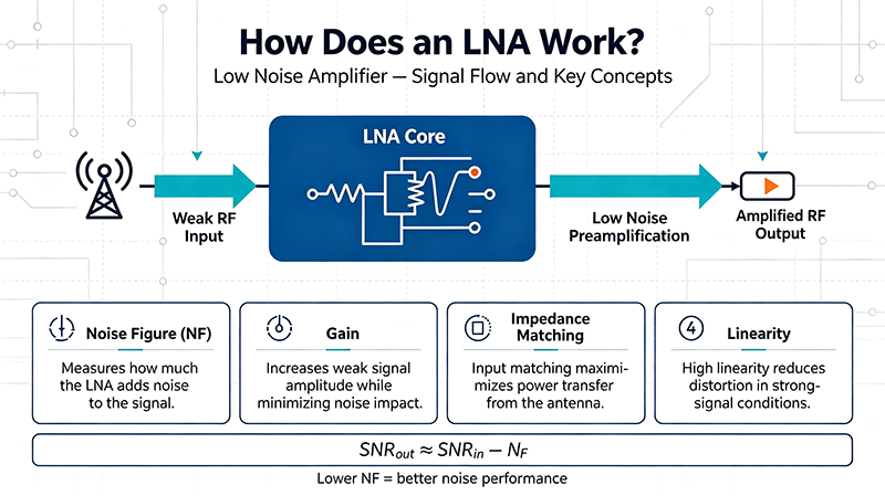
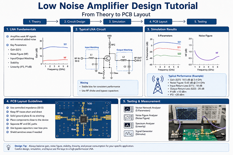
An LNA operates by presenting an input matching network that minimizes noise contribution, while biasing the active device in its low-noise region. The transistor converts DC power into RF gain, amplifying the incoming signal while injecting only minimal thermal and shot noise. Output matching is then optimized for gain, linearity, and impedance. The result is a compact, stable gain block that can recover signals buried below the noise floor of any downstream stage.

LNA Noise Figure

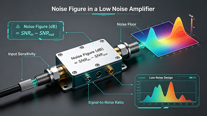
Noise Figure (NF) quantifies how much the LNA degrades the signal-to-noise ratio. Expressed in dB, it is calculated as 10·log10(SNR_in / SNR_out). Sub-1 dB NF is achievable in GaAs designs below 6 GHz; 1.5-3 dB is typical for mmWave LNAs. Because the LNA dominates cascaded NF, every fraction of a decibel matters for long-range, high-throughput links.

LNA Gain

Gain measures the amplification from input to output, typically 15-25 dB for general-purpose LNAs. Sufficient gain is required to overcome downstream noise, but excessive gain can saturate later stages and reduce dynamic range. Gain flatness across the operating band is equally important for wideband systems such as 5G and radar.

LNA IP3

Third-Order Intercept Point (IP3) is the key linearity metric. It indicates how well the LNA handles strong nearby interferers without generating intermodulation products that fall in-band. Higher OIP3 means stronger blocker tolerance, which is essential in dense urban cellular and EW environments.

LNA P1dB

The 1 dB Compression Point (P1dB) marks the input (or output) power at which gain compresses by 1 dB from its small-signal value. It defines the upper edge of the LNA's linear operating region. P1dB is roughly 10 dB below IP3 in most well-designed amplifiers.

LNA Stability

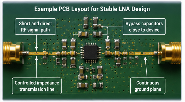
Stability ensures the amplifier does not oscillate under any combination of source and load impedance. Designers use the Rollet factor (K) and the auxiliary measure (B) to verify unconditional stability. Source degeneration, feedback resistors, and carefully laid-out PCBs all contribute to a stable design across frequency, temperature, and supply variation.

LNA VSWR

Voltage Standing Wave Ratio (VSWR) measures how well the input and output ports are matched to 50 ohms. Lower VSWR reduces signal reflection, improves power transfer, and protects upstream filters and antennas. Typical LNA VSWR is 1.5:1 or better.

LNA S Parameters

Scattering parameters fully characterize the small-signal RF behavior of an LNA across frequency:

Parameter Meaning
S11 Input return loss (input match)
S21 Forward gain (the LNA's amplification)
S12 Reverse isolation (feedback path)
S22 Output return loss (output match)

Together they define gain, match, stability, and group delay behavior of the amplifier.

Application Cluster

Use Cases

LNA for 5G

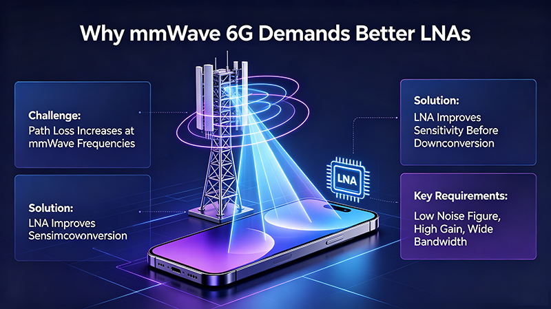
Sub-6 GHz and mmWave 5G base stations, small cells, and massive MIMO arrays rely on LNAs with sub-2 dB NF, wide bandwidth, and high linearity to maximize cell edge throughput and capacity.

LNA for Radar

Automotive 77-79 GHz radar, defense phased arrays, and weather radar need LNAs with low NF, high gain, and excellent phase noise performance for accurate target detection.

LNA for Satellite Communication

Satellite ground terminals and space-borne payloads use cryogenic-capable, ultra-low-NF LNAs (often GaAs pHEMT or InP HEMT) to receive faint signals from orbit.

LNA for SDR

Software-defined radios depend on wideband LNAs that cover multiple bands while preserving signal integrity for digital demodulation and spectrum sensing.

LNA for GNSS

GPS, GLONASS, BeiDou, and Galileo receivers use highly integrated LNAs with sub-1.5 dB NF to track weak satellite signals even in challenging urban canyons.

LNA for Microwave Receivers

Point-to-point microwave links, electronic warfare receivers, and telemetry systems all leverage microwave-band LNAs for low-noise front-end amplification across C, X, Ku, Ka, and beyond.

Selection Cluster

How to Choose

How to Choose an LNA

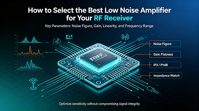
Start with four key parameters: frequency range, noise figure, gain, and linearity. Then narrow by power consumption, package, ESD robustness, and cost. Always verify the LNA is stable across your full band and supply range, and check that its input match works with your upstream filter or antenna.

LNA Frequency Range

Select an LNA whose specified frequency band fully covers your operating band with margin for filter roll-off and tuning. Narrow-band LNAs generally achieve better NF, while wideband LNAs offer flexibility for multiband or software-defined systems.

LNA Gain vs Noise Figure

Increasing gain improves cascaded NF by suppressing downstream noise, but it reduces linearity and dynamic range. Use Friis' formula to find the optimal gain that balances sensitivity with strong-signal handling.

LNA IP3 vs P1dB

P1dB marks the onset of compression, while IP3 (typically ~10 dB above P1dB) describes two-tone intermodulation behavior. In blocker-rich environments, prioritize high IP3. In single-tone, narrowband applications, P1dB may be the more relevant metric.

High-Frequency LNA Selection Guide

For frequencies above 20 GHz, prioritize GaAs pHEMT, GaN HEMT, or InP HEMT processes with proven mmWave performance. Evaluate package parasitics, on-chip matching, and the availability of evaluation boards at the exact band of interest.

Band Recommended Process Typical NF
Sub-6 GHz SiGe HBT, RF CMOS, GaAs 0.5 - 1.5 dB
6 - 20 GHz GaAs pHEMT, SiGe 1.0 - 2.0 dB
24 - 44 GHz (5G mmWave) GaAs, SiGe BiCMOS 1.5 - 3.0 dB
60 - 77 GHz (Automotive Radar) SiGe BiCMOS, GaAs 2.0 - 4.0 dB
94 GHz+ (Defense, Imaging) InP HEMT, GaN 2.5 - 5.0 dB

Commercial Cluster

Suppliers & Services

Low Noise Amplifier Manufacturer

Partnering with a dedicated LNA manufacturer ensures access to in-house MMIC design, advanced packaging, and full electrical/thermal/reliability testing from DC to mmWave.

RF LNA Manufacturer

RF LNA specialists deliver catalog and custom solutions across cellular, Wi-Fi, IoT, and industrial bands with proven high-volume supply chains.

Microwave LNA Manufacturer

Microwave LNA manufacturers focus on C through W bands, serving satellite, radar, EW, and scientific markets with hermetic and space-grade options.

Custom LNA

When off-the-shelf parts fall short, custom LNA design services provide optimized NF, gain, linearity, and packaging tailored to your exact system requirements.

High Frequency LNA Supplier

High-frequency LNA suppliers specialize in mmWave and sub-mmWave solutions, offering evaluation boards, datasheets, and reference designs to accelerate integration.

Frequently Asked Questions

Why is the LNA always placed first in the receiver chain?
Because Friis' formula shows that the first stage dominates the cascaded noise figure. Placing the lowest-noise, highest-gain stage at the front yields the best overall sensitivity.
What is the typical noise figure of a modern LNA?
Below 1 dB for sub-6 GHz GaAs designs, and 1.5-3 dB for mmWave LNAs operating from 24 to 77 GHz.
Can I cascade two LNAs to improve noise figure?
The second stage only marginally reduces total NF. It also doubles power consumption and can degrade linearity, so single-stage LNAs with adequate gain are usually preferred.
How do I protect an LNA from ESD or strong interferers?
Add input ESD diodes, a limiter, or a switched attenuator ahead of the LNA. Ensure the limiter's insertion loss is acceptable in normal operation.
What is the difference between LNA and PA?
An LNA amplifies weak received signals with minimum noise; a Power Amplifier (PA) boosts outgoing transmit signals with maximum efficiency and output power.

Looking for the Right LNA for Your System?

From catalog parts to fully custom designs, our team supports every stage of your low-noise amplifier selection and integration.

Request a Quote

About the Author — MeiXun Team

Wang

Chief Engineer Wang

High-tech Enterprise, Feifeng Talent

Chief Engineer Wang graduated with a master's degree in high-power microwave from the Institute of Electronics, University of Chinese Academy of Sciences.

View Full Profile
Wang

Chief Engineer Wang

High-tech Enterprise, Feifeng Talent

Chief Engineer Wang graduated with a master's degree in high-power microwave from the Institute of Electronics, University of Chinese Academy of Sciences.

In the same year, he joined CETC 40/41 for work and study. He has been committed to the design and development of microwave switches for a long time.

He has applied for 27 patents as the first inventor in the microwave switch field, with 6 authorized invention patents and 14 utility model patents.

The products he developed cover various application platforms such as civilian testing, vehicle-mounted, shipborne, airborne, and missile-borne.

RF Microwave Switch RF Switch Coaxial Switch PIN Diode Switch Low Noise Amplifier Waveguide Switch PIN Switch Microwave Switch