

























Selecting the optimal RF power divider is a critical design decision in microwave systems, signal processing networks, and test setups.
Aug 07 ,26


5G communication testing, wireless terminal automated testing
Aerospace communication systems
Precision measurement equipment, radio frequency signal control of radar transmitters
Communication and navigation systems
Optical communication module-related testing
Interconnection of wireless communication base stations
In modern radio frequency (RF) and microwave engineering, signal distribution plays a pivotal role in system performance. A Broadband Power Divider is an essential passive component designed to split an input signal into two or more output signals across a wide frequency range while maintaining impedance matching and minimal signal loss.
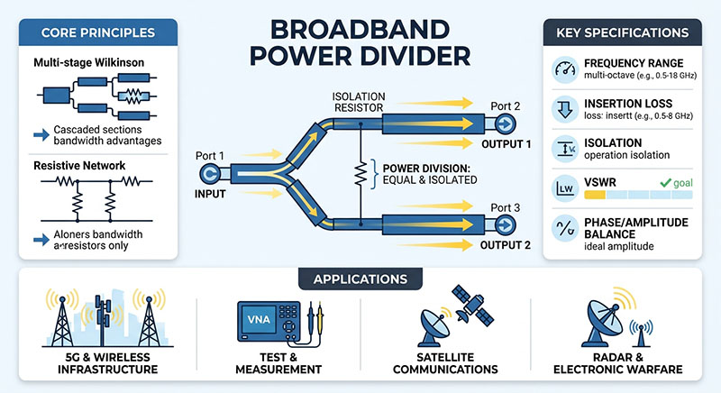
Key Takeaway: Unlike narrowband splitters, broadband power dividers operate efficiently across multi-octave bandwidths, making them indispensable in modern 5G, satellite communications, and radar applications.
A power divider (or power splitter) accepts a single RF signal and splits it into multiple equal or unequal paths. A device is classified as "broadband" when it maintains consistent electrical performance—such as low insertion loss, high isolation, and good return loss—over a broad frequency spectrum (often ranging from hundreds of megahertz to tens of gigahertz).
Broadband power dividers rely on specialized transmission line architectures to achieve wide bandwidth performance. The two most common topologies include:
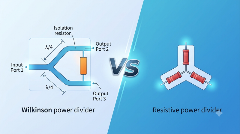
Standard Wilkinson dividers use quarter-wave transmission lines to provide matching and isolation between output ports. To achieve broadband operation, engineers utilize multi-stage designs. By cascading multiple quarter-wave sections with isolation resistors, the operational bandwidth increases significantly across several octaves.
Resistive dividers use a network of precision resistors to split signals evenly from DC to extremely high microwave frequencies. While they offer the broadest frequency coverage, they introduce inherent power attenuation (typically 6 dB for a 2-way split) and lack port-to-port isolation compared to reactive designs.
When selecting or designing a broadband power divider, engineers evaluate several core parameters:
| Specification | Description | Target Value |
|---|---|---|
| Frequency Range | The operational bandwidth where specs are met. | e.g., 0.5 GHz – 18 GHz |
| Insertion Loss | Signal power lost beyond the nominal split ratio. | As low as possible (< 1.0 dB ideal) |
| Isolation | Attenutation between output ports to prevent crosstalk. | > 20 dB typical |
| VSWR / Return Loss | Measures impedance matching at input/output ports. | VSWR < 1.5:1 typical |
| Phase/Amplitude Balance | Equality of output signal magnitude and phase phase. | Minimizes phase shift error |
Broadband power dividers serve as fundamental building blocks across advanced communications and test systems:
Selecting the right broadband power divider requires balancing frequency bandwidth, power handling, insertion loss, and isolation. As wireless networks demand wider bandwidths and higher frequency operation, multi-stage Wilkinson and advanced microstrip or stripline power dividers remain critical components in high-performance RF architecture.

High-tech Enterprise, Feifeng Talent
Chief Engineer Wang graduated with a master's degree in high-power microwave from the Institute of Electronics, University of Chinese Academy of Sciences.
View Full Profile