What is an N-Type Connector?

The N-type connector is one of the most widely used medium-power coaxial RF connectors. Designed in the 1940s by Paul Neill at Bell Labs, the N connector offers rugged threaded coupling, low VSWR, and reliable performance from DC to 11 GHz (precision versions reach 18 GHz).

Quick Answer

The N-type connector (or "Type N") is a threaded, weatherproof coaxial RF connector designed for medium-power applications up to about 11 GHz. It is the standard interconnect for cellular base stations, broadcast transmitters, test equipment, RF antennas, and any system needing reliable performance with low loss and high power handling. N connectors come in 50 Ω (most common) and 75 Ω (broadcast video) versions.
Origin and Naming

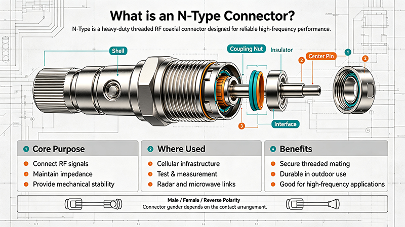
What is an N-Type Connector

The N connector was invented by Paul Neill at Bell Telephone Laboratories in 1942. It is named after its inventor (Neill) — a common practice for RF connectors (others include SMA for SubMiniature version A, and BNC for Bayonet Neill-Concelman). The original design solved the need for a robust, weatherproof connector for microwave systems during World War II.

Through decades of refinement, the N connector became the de facto standard for medium-power RF up to 11 GHz and remains ubiquitous in cellular, broadcast, defense, and test equipment.

Mechanical Design

N-Type Connector Cross-Section

N Plug (Male) N Jack (Female) Center Pin Center Socket Thread

N connectors use a 5/8"-24 threaded coupling. The outer contact also uses slots and fingers for a robust, low-loss connection.

N connectors use a 5/8"-24 UNEF threaded interface. The plug has a center pin and threaded outer body; the jack has a center socket and threaded outer body with a hex flange for mounting. The coupling nut is tightened with a wrench to the recommended torque (typically 12 – 15 in-lbs for the standard N).

Electrical Performance

Specification Typical Value
Frequency Range (50 Ω) DC – 11 GHz (precision: 18 GHz)
Frequency Range (75 Ω) DC – 1.5 GHz
VSWR (DC – 11 GHz) ≤ 1.30:1 (precision ≤ 1.10:1)
Insertion Loss (DC – 11 GHz) ≤ 0.15 dB
Dielectric Withstanding Voltage 2,500 V RMS
Insulation Resistance ≥ 5 GΩ
Center Contact Resistance ≤ 1 mΩ
Outer Contact Resistance ≤ 0.2 mΩ
RF Leakage ≥ −90 dB

Mechanical Specifications

Specification Value
Impedance 50 Ω standard, 75 Ω available
Threading 5/8"-24 UNEF
Mating Cycles 500 minimum
Coupling Torque 12 – 15 in-lbs (1.4 – 1.7 N·m)
Body Material Brass, nickel-plated or stainless steel
Center Contact Gold-plated brass or beryllium copper
Dielectric PTFE (Teflon)
Operating Temperature −65 °C to +165 °C
Weatherproof Yes (with proper gaskets)

Types and Variants

Standard

Standard N (50 Ω)

The most common type. Used from DC to 11 GHz in cellular, broadcast, and test equipment.

Precision

Precision N

Tighter tolerances for VSWR. Used in metrology and VNA test ports up to 18 GHz.

75 Ω

N 75 Ω

Used in CATV and broadcast video. Different center pin diameter; not intermateable with 50 Ω N.

High Power

High-Power N

Larger body, better dielectric, and cooling features for kilowatt applications. Used in broadcast transmitters.

Reverse Polarity

Reverse-Polarity N (RP-N)

Swapped center pin/socket. Used in some Wi-Fi and legacy equipment to prevent unauthorized antenna changes.

Push-On

Quick-Connect N

Snap-on version for faster mating. Reduced mechanical robustness and lower frequency range.
Key Advantages

  • Durable threaded coupling: holds firmly under vibration and rough handling.
  • Weatherproof: suitable for outdoor installations when properly sealed.
  • Low loss: excellent performance up to 11 GHz.
  • High power handling: up to several kilowatts CW in special variants.
  • Wide standard adoption: ubiquitous in cellular, broadcast, and defense.
  • Mature ecosystem: cables, adapters, attenuators, terminations all widely available.

Limitations

  • Size and weight: larger than SMA and SMB.
  • Mating time: threaded coupling takes longer than snap-on connectors.
  • Frequency cap: standard N reaches 11 GHz; above this, use SMA, 3.5 mm, or 2.92 mm.
  • Torque wrench required: needs proper installation to maintain performance.

N vs SMA vs TNC vs BNC

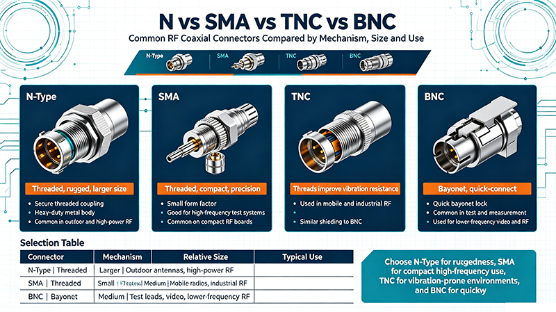
N vs SMA vs TNC vs BNC

N-Type

  • Frequency: DC – 11 GHz
  • Power: ~ 500 W CW
  • Threading: 5/8"-24
  • Use: cellular, broadcast, test

SMA

  • Frequency: DC – 18 GHz
  • Power: ~ 200 W CW
  • Threading: 1/4"-36
  • Use: lab, instrumentation
Connector Frequency Power Coupling Use
N-Type DC – 11 GHz 500 W CW Threaded Cellular, broadcast, defense
SMA DC – 18 GHz 200 W CW Threaded Lab, instrumentation
TNC DC – 11 GHz 500 W CW Threaded (smaller than N) Wi-Fi antennas, GPS
BNC DC – 4 GHz 100 W CW Bayonet Test, video, low-frequency RF
7-16 DIN DC – 7.5 GHz 2,800 W CW Threaded High-power cellular
Tip: For high-power applications (kW range), consider 7-16 DIN connectors. For higher frequency (above 11 GHz), use SMA, 3.5 mm, 2.92 mm, or 2.4 mm connectors.

Real-World Applications

  • Cellular base stations: standard RF connector for 4G and 5G FR1 macro cells.
  • Broadcast transmitters: FM, TV, and DAB transmitters use N for outputs up to several kW.
  • RF antennas: outdoor antennas for cellular, Wi-Fi, and microwave links.
  • Test equipment:
  • signal generators, spectrum analyzers, and VNAs.
  • Public safety radios: land mobile radio and two-way radio systems.
  • Radar: L-band and S-band radar systems.
  • Microwave point-to-point links: backhaul links for cellular and private networks.

How to Choose an N Connector

  1. Determine the impedance — 50 Ω for most RF, 75 Ω for video.
  2. Choose the right gender (plug or jack) for your panel or cable.
  3. Match the connector to the cable type (RG-58, RG-213, LMR-400, etc.).
  4. Select the right mounting style: bulkhead, panel, or in-line.
  5. Verify the rated frequency covers your application.
  6. For outdoor use, choose weatherproof versions with proper sealing.

Installation Best Practices

  • Use a torque wrench to tighten to the manufacturer's spec.
  • Clean connectors with isopropyl alcohol before mating.
  • Inspect pins and sockets for damage before each connection.
  • Use heat-shrink boots for outdoor connections.
  • Avoid bending cables sharply near the connector.
  • Cap unmated connectors to keep out contamination.

Common Mistakes

  • Over-tightening: damages threads and reduces life.
  • Under-tightening: poor electrical contact and arcing at high power.
  • Mating 50 Ω and 75 Ω versions: mechanically possible but causes reflections.
  • Forgetting weatherproofing outdoors: moisture corrodes the dielectric.
  • Using N above its rated frequency: VSWR and loss increase dramatically.

Key Takeaways

  • The N-type connector is a rugged, threaded RF connector for DC – 11 GHz.
  • Designed by Paul Neill at Bell Labs in 1942, named after its inventor.
  • Available in 50 Ω (most common) and 75 Ω (video) versions.
  • Standard for cellular base stations, broadcast, and test equipment.
  • Use a torque wrench for installation; respect power and frequency limits.

Frequently Asked Questions

What is an N-type connector?

The N-type connector is a threaded, medium-power coaxial RF connector designed by Paul Neill in 1942. It operates from DC to 11 GHz (precision versions to 18 GHz) and is used for cellular, broadcast, test, and defense applications.

What does the "N" stand for?

The "N" stands for Neill, the surname of its inventor Paul Neill at Bell Labs.

What is the maximum frequency of N-type?

Standard N connectors are rated to 11 GHz. Precision N connectors (e.g., APC-7) reach 18 GHz.

Can I mate a 50 Ω N with a 75 Ω N?

Mechanically yes, but the impedance mismatch causes reflections and degraded performance. Use the correct impedance version for your system.

What is the difference between N and 7-16 DIN?

Both are threaded medium-power RF connectors. 7-16 DIN handles higher power (~ 2,800 W CW) and has lower intermodulation, making it preferred for cellular macro cells. N is more general-purpose.

  • Radio Frequency Connector Classification
    Comprehensive guide to radio frequency connector classification. Learn about SMA, BNC, N-Type, TNC, MCX connectors, their applications, specifications, and how to choose the right RF connector.
    Sep 08 ,26
  • Optimizing RF Connector: Performance Degradation Due to Wear and Tear
    RF connectors are critical interfaces in microwave, wireless communication, radar, test and measurement, satellite, and high-freque...
    Sep 08 ,26
  • The Difference Between SMB and SMA connector
    The difference between SMB and SMA connectors — frequency range, mechanical design, electrical performance, applications, and how to choose the right one for your RF system.
    Sep 08 ,26
  • What Are 1.5-3.5 Connectors?
    1.5-3.5 connectors are high-frequency coaxial RF connectors designed for demanding microwave and millimeter-wave applications.
    Sep 04 ,26
  • What are QMA Connectors?
    What are QMA connectors? Learn about the QMA quick-lock RF connector — its features, electrical performance, mechanical specifications, and how it compares to SMA and other RF connectors.
    Sep 03 ,26
  • What Is an SMB Connector? A Comprehensive Guide
    Learn what an SMB connector is, its specifications, applications, and how it compares to SMA and SMC connectors in this comprehensive guide.
    Aug 24 ,26
  • What Is an RF Connector?
    In this guide, you will learn what an RF connector is, how it works, the different types of RF connectors, their applications, and how to choose the right connector for your RF or microwave system.
    Aug 22 ,26
  • What Is an SMA Connector? Everything You Need to Know
    An SMA connector, short for SubMiniature version A connector, is a compact threaded coaxial RF connector widely used for transmitting high-frequency signals.
    Aug 22 ,26
  • How to Choose the Right RF Connector for Your Application
    Learn how to select RF connectors based on frequency range, impedance, VSWR, power handling, connector types, mechanical constraints, and environmental conditions.
    Aug 14 ,26

About the Author — MeiXun Team

Wang

Chief Engineer Wang

High-tech Enterprise, Feifeng Talent

Chief Engineer Wang graduated with a master's degree in high-power microwave from the Institute of Electronics, University of Chinese Academy of Sciences.

View Full Profile
Wang

Chief Engineer Wang

High-tech Enterprise, Feifeng Talent

Chief Engineer Wang graduated with a master's degree in high-power microwave from the Institute of Electronics, University of Chinese Academy of Sciences.

In the same year, he joined CETC 40/41 for work and study. He has been committed to the design and development of microwave switches for a long time.

He has applied for 27 patents as the first inventor in the microwave switch field, with 6 authorized invention patents and 14 utility model patents.

The products he developed cover various application platforms such as civilian testing, vehicle-mounted, shipborne, airborne, and missile-borne.

RF Microwave Switch RF Switch Coaxial Switch PIN Diode Switch Low Noise Amplifier Waveguide Switch PIN Switch Microwave Switch