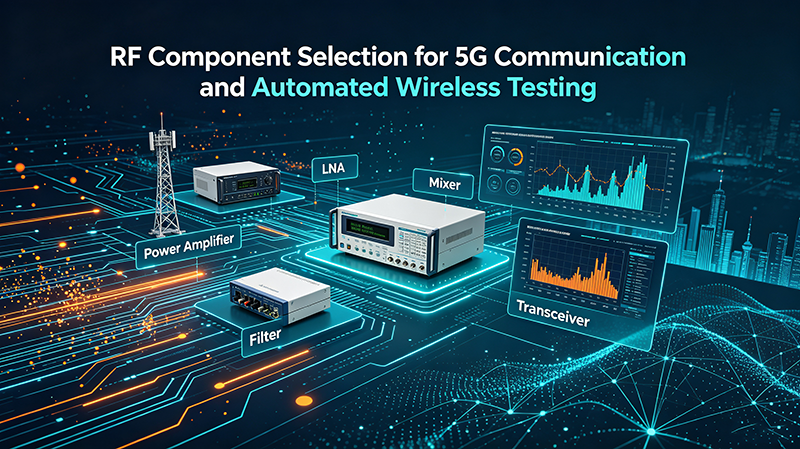
RF Component Selection for 5G Communication and Automated Wireless Testing
Quick Answer
For 5G, choose RF components that cover your band (FR1 sub-7.125 GHz or FR2 24 – 52 GHz), meet linearity (ACPR / EVM) for OFDM, support required bandwidths up to 400 MHz or 800 MHz, and integrate well with digital interfaces for beamforming and DPD. For automated wireless testing, prioritize repeatable, software-controlled components: programmable attenuators, fast switches, calibration-grade filters, and stable phase-matched paths.
5G Frequency Bands
| Range | Frequency | Bandwidth | Typical Component Challenge |
|---|---|---|---|
| FR1 low | 410 – 7125 MHz | 5 – 100 MHz | Mature LDMOS / GaN PAs available |
| FR1 mid | 2.5 – 4.2 GHz | 100 – 200 MHz | GaN for high-power macro |
| FR1 high | 24.25 – 29.5 GHz | 200 – 400 MHz | GaN / GaAs MMICs, phased arrays |
| FR2 | 37 – 43.5 GHz | 200 – 800 MHz |
mmWave beamforming ICs, AiP modules
|
5G Component Selection Flow
- Define band and bandwidth: FR1 sub-7.125 GHz uses LDMOS / GaN; FR2 mmWave uses GaAs / SiGe / CMOS AiP.
- Set power and linearity specs: ACPR / EVM targets based on modulation (QPSK to 1024-QAM).
- Choose semiconductor technology: GaN for power, GaAs for low-noise, SiGe for compact integration.
- Pick topology: Doherty for cellular efficiency, phased-array T/R for mmWave.
- Validate end-to-end: bench test under realistic 5G NR waveforms and temperature.
Key 5G Components
1. Power Amplifiers (PA)
For FR1 macro cells, GaN Doherty PAs deliver 60 – 70 % PAE at 8 dB back-off, with DPD pushing ACPR below −55 dBc. For mmWave, AiP modules integrate the PA, switch, LNA, and beamforming in a single package.
2. Low-Noise Amplifiers (LNA)
mmWave receivers require NF below 3 dB at 28 GHz. SiGe BiCMOS LNAs are common in AiP modules; GaAs pHEMT LNAs offer better noise but cost more.
3. Filters
Surface-acoustic-wave (SAW), bulk-acoustic-wave (BAW), and integrated passive device (IPD) filters dominate FR1. mmWave uses integrated filters in the AiP or in the RFIC itself.
4. Antennas
FR1 uses patch antennas or cross-polarized panels. FR2 requires phased-array antennas with up to 1024 elements per module, integrating both RFIC and patch array.
5. Switches
PIN diodes handle high-power FR1 transmit/receive switching. mmWave uses CMOS switches integrated into the RFIC for fast, low-loss T/R switching.
6. Phase Shifters
Active and passive phase shifters integrated in the RFIC support beam steering. Resolution of 5 – 6 bits (≈ 5° step) is typical.
7. Mixers
mmWave upconverters and downconverters use I/Q architectures for direct conversion or low-IF. GaAs and SiGe BiCMOS are the dominant technologies.
Key Specifications for 5G
| Specification | Why It Matters | Typical Target |
|---|---|---|
| Operating Band | Must match FR1 / FR2 | FR1 or FR2 |
| Bandwidth | Carriers up to 400 – 800 MHz | ≥ 200 MHz typical |
| ACPR / EVM | 5G NR spectral mask | ACPR < −50 dBc; EVM < 4 % |
| Efficiency (PAE) | Thermal / OPEX | ≥ 50 % at back-off |
| Latency | URLLC and gaming | < 1 ms in some cases |
| Beamforming | FR2 MIMO | 64 – 1024 elements |
| Phase Noise | High-order QAM | −95 dBc/Hz @ 100 kHz |
FR1 vs. FR2 Component Differences
FR1 (Sub-7 GHz)
- LDMOS or GaN PAs
- Discrete filters (SAW / BAW)
- Patch or cross-pol antennas
- Mature supply chain
- Long-range macro cells
- Cost-effective
FR2 (mmWave 24 – 52 GHz)
- GaAs / SiGe / CMOS AiP
- Integrated on-chip filters
- Phased-array antennas
- Newer supply chain
- Short-range small cells
- Higher BOM cost
Automated Wireless Testing (ATE)
Automated test equipment for 5G must verify RF performance across many bands, modulation schemes, and temperature conditions — quickly and repeatably. The major components of an ATE RF test bench are:
- Vector signal generator (VSG): produces 5G NR waveforms at precise frequencies and power levels.
- Vector signal analyzer (VSA): captures and demodulates signals to compute EVM, ACPR, and block error rate.
- Programmable attenuator: sets signal levels across wide dynamic range (often 0 – 120 dB).
- RF switch matrix: routes signals to multiple DUT ports or test antennas.
- Calibration-grade filters: remove harmonics and image frequencies.
- Reference antennas or cables: for OTA or conducted testing.
- Shielded test enclosures: isolate DUT from external interference.
Key ATE Components
Programmable Attenuator
0 – 120 dB range, 0.1 dB step, fast settling. Used for receiver sensitivity and power calibration.
RF Switch Matrix
Routes signals among multiple DUT ports. SP4T – SP32T and matrix configurations.
Calibration Filter
Removes harmonics and image frequencies from sources and reference signals.
Phase-Stable Cable
Low-loss, phase-matched cables for repeatable measurements across temperature.
Calibration Adapters
Precision adapters (SMA, 3.5 mm, 2.92 mm) for VNA calibration.
Component Selection Criteria
For 5G Infrastructure
- Frequency band coverage (FR1 or FR2).
- Power efficiency and linearity (DPD compatibility).
- Thermal performance and packaging.
- Beamforming capability (mmWave).
- Reliability (MTBF) and operating temperature.
For Automated Wireless Testing
- Software control interface (USB, Ethernet, GPIB, SPI).
- Switching speed and settling time.
- Repeatability across temperature.
- Phase and amplitude stability.
- Calibration cycle and traceability.
Integration Best Practices
- Choose components with documented S-parameter data for simulation.
- Use 50 Ω impedance throughout the test path.
- Provide adequate thermal management for high-power components.
- Plan EMI/EMC shielding from the start — 5G and test equipment radiate easily.
- Validate components under realistic waveforms, not just CW.
- Document calibration procedures and intervals.
Common Mistakes
- Mixing FR1 and FR2 components: sub-7 GHz parts do not work at 28 GHz.
- Ignoring bandwidth: 5G NR carriers exceed 100 MHz; narrowband parts distort.
- Overlooking DPD: linear PAs without DPD fail 5G spectral masks.
- Skipping phase matching: beamforming requires tight phase control across elements.
- Using consumer-grade cables in test: unstable phase corrupts measurements.
- Forgetting calibration: ATE without regular cal gives wrong answers.
Validation & Acceptance
- Verify small-signal S-parameters on a calibrated VNA.
- Measure EVM and ACPR under representative 5G NR waveforms.
- Test thermal performance at maximum duty cycle.
- Confirm software control and timing for ATE applications.
- Validate beamforming performance across scan angles.
- Run reliability tests under temperature, humidity, and vibration.
Key Takeaways
- 5G RF component choice depends on band (FR1 vs FR2), power, and linearity.
- GaN dominates FR1 power; GaAs / SiGe / CMOS rule FR2 mmWave.
- Beamforming and DPD are essential for modern 5G performance.
- Automated wireless testing needs software-controlled, repeatable components.
- Phase stability, calibration, and shielding are as critical as raw specs.
Frequently Asked Questions
What is the difference between FR1 and FR2 in 5G?
FR1 is sub-7.125 GHz, similar to 4G bands, used for long-range coverage. FR2 is mmWave (24 – 52 GHz), used for short-range high-capacity cells and requires beamforming.
Which semiconductor technology is best for 5G PAs?
GaN Doherty PAs are standard for FR1 macro cells. GaAs MMIC and SiGe BiCMOS are used for FR2 mmWave phased arrays, often integrated into antenna-in-package modules.
Why is DPD important for 5G?
DPD corrects AM/AM and AM/PM distortion in the PA, allowing higher efficiency while meeting 5G NR spectral mask requirements. Without DPD, even high-linearity PAs fail ACPR tests.
What components are needed for an ATE test bench?
A typical 5G ATE bench includes a vector signal generator, vector signal analyzer, programmable attenuator, switch matrix, calibration filters, phase-stable cables, and shielded enclosures.
What is the biggest challenge in mmWave testing?
Path loss is enormous, requiring beamforming alignment and OTA test setups. Connector repeatability also degrades above 40 GHz; many mmWave tests use waveguide or probes.

-
DATE June 9-11, 2026 LOCATION Thomas M. Menino Convention & Exhibition Center Boston, MAMay 26 ,26
-
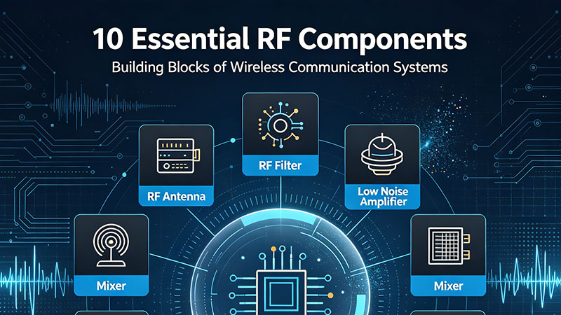
Radio frequency and microwave systems depend on a wide range of specialized components to generate, control, transmit, receive, filter, divide, amplify, and switch high-frequency signals.Aug 26 ,26
-
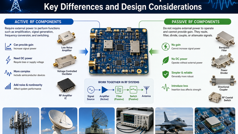
Active and passive RF components play fundamentally different roles in radio-frequency and microwave systems.Aug 25 ,26
About the Author — MeiXun Team
Chief Engineer Wang
High-tech Enterprise, Feifeng Talent
Chief Engineer Wang graduated with a master's degree in high-power microwave from the Institute of Electronics, University of Chinese Academy of Sciences.
View Full Profile- RF Switch Circuit Diagram
- RF Switch
- Ohm's Law
- dBm to Watt
- mW to dBm
- Wavelength to Frequency
- RF Connector
- SMA Connector
- RF Switch Module
- RF Coupler
- RF PIN Switch
- Microwave Coaxial Switch
- PIN Switch
- Coaxial RF Switch
- Waveguide Switch
- Microwave Switch
- Low Noise Amplifier
- PIN Diode Switch
- Coaxial Switch
- RF Microwave Switch
- SPST Switch