


























DATE
June 9-11, 2026
LOCATION
Thomas M. Menino Convention & Exhibition Center
Boston, MA
May 26 ,26


5G communication testing, wireless terminal automated testing
Aerospace communication systems
Precision measurement equipment, radio frequency signal control of radar transmitters
Communication and navigation systems
Optical communication module-related testing
Interconnection of wireless communication base stations
Radio frequency and microwave systems depend on a wide range of specialized components to generate, control, transmit, receive, filter, divide, amplify, and switch high-frequency signals. Whether you are designing a wireless communication system, radar platform, satellite terminal, RF test setup, or IoT device, understanding the function and selection criteria of essential RF components is critical.
Unlike low-frequency electronic circuits, RF circuits are highly sensitive to impedance matching, insertion loss, frequency response, parasitic effects, power handling, and electromagnetic interference. Selecting the wrong RF component can reduce signal quality, increase reflections, introduce noise, or cause complete system failure.
In this guide, we explain 10 essential RF components every engineer should know, including their functions, key specifications, common applications, and important selection considerations.
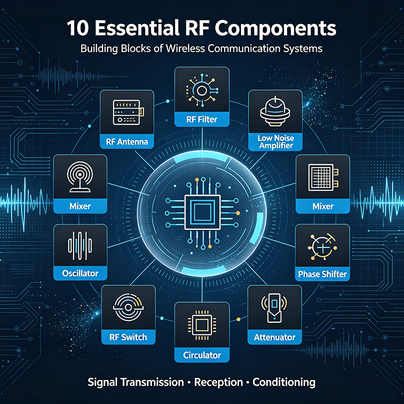
An RF system is only as reliable as the components used to build it. At high frequencies, even short PCB traces, connectors, and component packages can significantly affect signal performance.
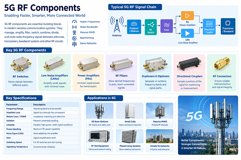
Engineers working with RF and microwave circuits need to understand how different components interact within the signal chain. A typical RF system may include an antenna, filter, amplifier, switch, coupler, attenuator, power divider, connector, and other passive or active devices.
Key principle: RF component selection should not be based on frequency alone. Engineers must also evaluate impedance, bandwidth, insertion loss, return loss, VSWR, isolation, linearity, noise figure, power handling, switching speed, and environmental requirements.
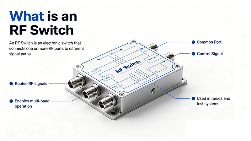
An RF switch controls the path of a radio frequency signal. It can connect one input to one or more outputs, disconnect a signal path, or route signals between different circuits.
Common RF switch configurations include SPST, SPDT, SP3T, SP4T, SP6T, and higher-throw designs. RF switches can be electromechanical, solid-state, PIN diode-based, MEMS-based, or implemented using semiconductor technologies.
Key specifications:
Typical applications: RF test systems, communication equipment, antenna switching, radar systems, and automated measurement systems.

A Low Noise Amplifier (LNA) amplifies weak RF signals while adding as little noise as possible. LNAs are typically installed near the front end of a receiver, where the received signal may be extremely weak.
Noise figure is one of the most important parameters because noise introduced at the beginning of a receiver chain can significantly affect the overall system sensitivity.
Key specifications:
Typical applications: satellite communication, GPS, radar receivers, wireless base stations, test equipment, and radio astronomy.

An RF power amplifier increases the power level of an RF signal before it is transmitted to an antenna or delivered to another high-power RF stage.
Power amplifiers are widely used in transmitters and must provide sufficient output power while maintaining acceptable efficiency, linearity, and signal quality.
Key specifications:
Typical applications: wireless transmitters, radar, satellite uplinks, electronic warfare, and industrial RF systems.
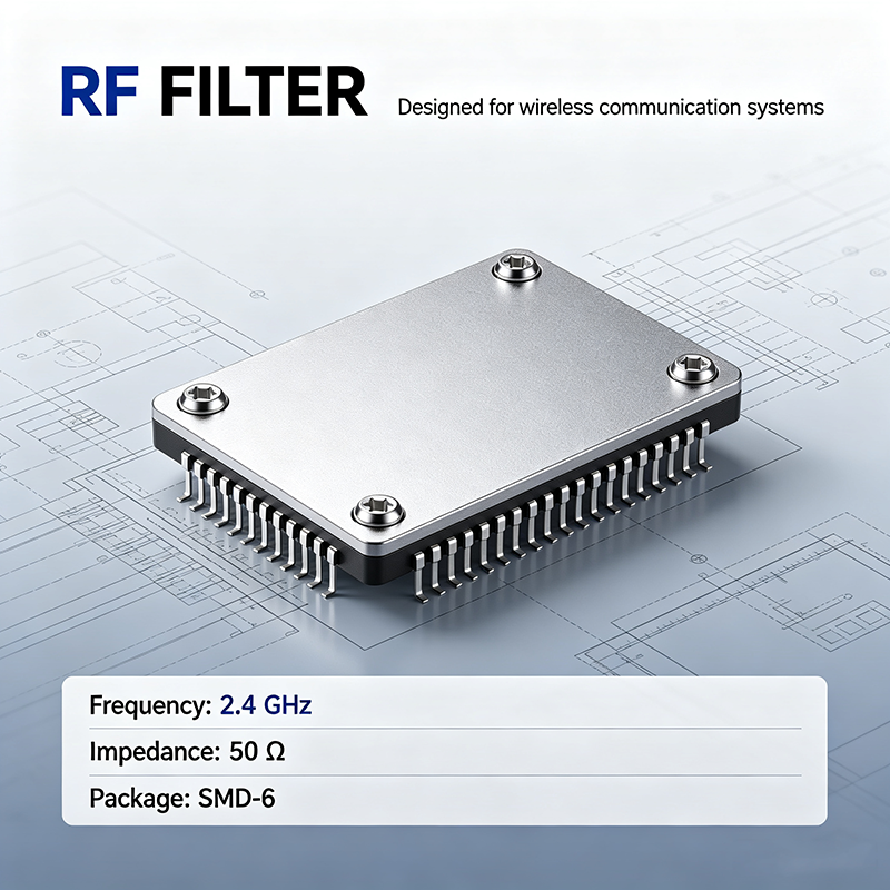
An RF filter allows desired frequencies to pass while reducing unwanted signals, noise, harmonics, or interference.
Common RF filter types include:
Filters are essential for controlling spectral content and protecting sensitive receiver circuits from unwanted high-power signals.
Key specifications:

An RF attenuator reduces signal power by a controlled amount without significantly distorting the signal waveform or frequency characteristics.
Attenuators are commonly used to protect sensitive equipment, control signal levels, improve impedance matching, and calibrate RF test systems.
Fixed attenuators provide a constant attenuation value, while variable and programmable attenuators allow engineers to adjust the signal level.
Key specifications:

A directional coupler samples a controlled portion of RF power traveling through a transmission line. It is one of the most useful passive components for RF measurement and monitoring.
Directional couplers can be used to measure forward power, reflected power, return loss, and VSWR without interrupting the main signal path.
Key specifications:
Typical applications: RF power monitoring, transmitter testing, antenna systems, radar, satellite communication, and laboratory measurement.

An RF power divider splits one input signal into two or more output signals. A power combiner performs the reverse function by combining multiple signals into one output.
Common designs include Wilkinson power dividers, resistive dividers, hybrid couplers, and multi-way power distribution networks.
Key specifications:
Typical applications: antenna arrays, distributed RF systems, power amplifier combining, communication networks, and RF test setups.
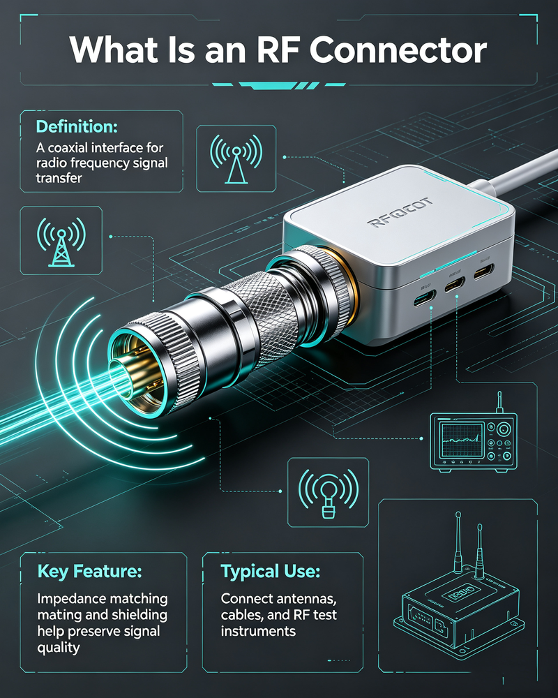
An RF connector provides a mechanical and electrical interface between RF cables, components, instruments, antennas, and systems.
At high frequencies, connector quality has a major impact on signal integrity. A poorly selected or damaged connector can increase insertion loss, reflections, and VSWR.
Common RF connector types include SMA, N-type, BNC, TNC, 2.92 mm, 2.4 mm, 1.85 mm, and SMP connectors.
Key specifications:

An RF mixer combines two frequencies to generate new frequencies. Mixers are essential for frequency conversion in transmitters and receivers.
For example, an intermediate-frequency signal can be mixed with a local oscillator signal to produce a higher-frequency RF output. In a receiver, an incoming RF signal can be converted to a lower intermediate frequency for easier processing.
Key specifications:
Typical applications: frequency converters, superheterodyne receivers, transmitters, radar, satellite communication, and spectrum analysis.
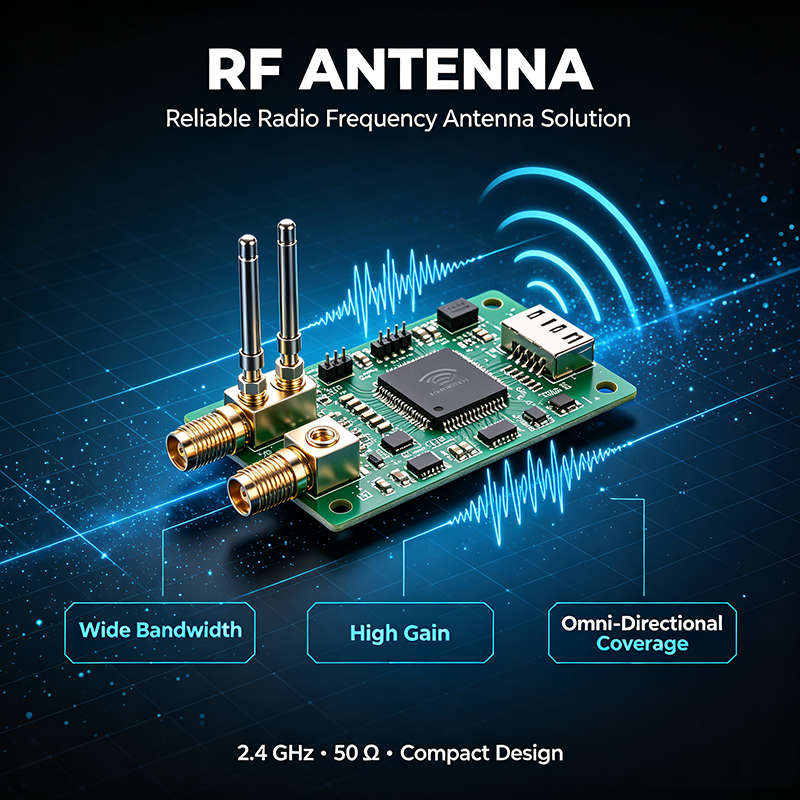
An antenna converts electrical RF energy into electromagnetic waves for transmission and converts received electromagnetic waves into electrical signals.
Antennas are fundamental components in nearly every wireless system. Their design affects coverage, gain, radiation pattern, polarization, bandwidth, and overall communication performance.
Key specifications:
Typical applications: cellular communication, Wi-Fi, satellite communication, GPS, radar, IoT, and wireless sensors.
| RF Component | Main Function | Important Parameters |
|---|---|---|
| RF Switch | Routes RF signals | Insertion loss, isolation, speed |
| Low Noise Amplifier | Amplifies weak signals | Noise figure, gain, IP3 |
| Power Amplifier | Increases RF output power | Output power, gain, efficiency |
| RF Filter | Controls frequency content | Bandwidth, rejection, insertion loss |
| RF Attenuator | Reduces signal power | Attenuation, accuracy, power rating |
| Directional Coupler | Samples RF power | Coupling, directivity, insertion loss |
| Power Divider | Splits or combines power | Isolation, balance, insertion loss |
| RF Connector | Connects RF components | Frequency, VSWR, power handling |
| RF Mixer | Converts frequencies | Conversion loss, IP3, isolation |
| Antenna | Transmits and receives RF energy | Gain, pattern, bandwidth |
When building an RF or microwave system, component selection should be based on the complete signal-chain requirement rather than individual specifications alone.
Engineering tip: In a high-performance RF system, individual component specifications must be evaluated together. For example, a low-noise amplifier cannot achieve the expected system sensitivity if it is preceded by a high-loss cable, switch, or filter.
RF components are electronic or passive devices designed to generate, control, transmit, receive, process, or measure radio frequency and microwave signals.
There is no single most important RF component. The required component depends on the system. However, antennas, amplifiers, filters, switches, connectors, and couplers are fundamental to many RF systems.
RF generally refers to electromagnetic frequencies used for radio communication, while microwave frequencies are commonly considered a higher-frequency portion of the RF spectrum. The exact classification may vary depending on the technical standard and application.
Proper impedance matching minimizes signal reflections and helps maximize power transfer between RF components. Poor matching can increase VSWR, return loss, and signal degradation.
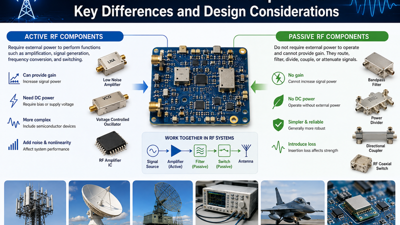
Active RF components require power and can provide amplification, gain, switching, or frequency conversion. Passive RF components do not provide gain and are commonly used for filtering, coupling, attenuation, power division, and signal interconnection.
Understanding essential RF components is the foundation of successful RF and microwave system design. RF switches control signal paths, LNAs improve receiver sensitivity, power amplifiers increase transmission power, filters remove unwanted frequencies, attenuators control signal levels, and directional couplers support accurate measurement and monitoring.
Power dividers, RF connectors, mixers, and antennas are equally important for distributing, interconnecting, converting, transmitting, and receiving high-frequency signals.
By understanding the functions and key specifications of these 10 essential RF components, engineers can make better design decisions, improve signal integrity, reduce system losses, and build more reliable RF and microwave solutions.


High-tech Enterprise, Feifeng Talent
Chief Engineer Wang graduated with a master's degree in high-power microwave from the Institute of Electronics, University of Chinese Academy of Sciences.
View Full Profile