


























DATE
June 9-11, 2026
LOCATION
Thomas M. Menino Convention & Exhibition Center
Boston, MA
May 26 ,26


5G communication testing, wireless terminal automated testing
Aerospace communication systems
Precision measurement equipment, radio frequency signal control of radar transmitters
Communication and navigation systems
Optical communication module-related testing
Interconnection of wireless communication base stations
Active and passive RF components play fundamentally different roles in radio-frequency and microwave systems. Understanding how they operate, how they affect signal performance, and how they interact within an RF signal chain is essential for designing reliable communication, radar, test, aerospace, satellite, and wireless systems.
Every RF and microwave system is built from a combination of components that generate, amplify, control, route, filter, divide, attenuate, or transmit electromagnetic signals. These components are generally divided into two major categories: active RF components and passive RF components.
The most important difference is that active components require an external power source to perform their intended function, while passive components generally operate without a separate DC power supply. However, the distinction is more than simply whether a component consumes power. Active and passive devices have different effects on gain, noise, linearity, frequency response, power handling, and overall RF system performance.
Active RF components are electronic devices that require electrical power and can influence a signal through amplification, frequency conversion, generation, switching, or other controlled electronic processes. These components typically contain semiconductor devices such as transistors, diodes, integrated circuits, or monolithic microwave integrated circuits.
An RF amplifier is one of the clearest examples of an active component. A low-level input signal enters the amplifier, and DC power supplies the additional energy required to produce a stronger output signal. The output RF power can therefore be greater than the input RF power, which is why the device provides gain.
Passive RF components operate without providing RF power gain. They are used to control the path, distribution, impedance, frequency content, phase, or amplitude of an RF signal. Although passive components do not amplify signals, they are critical to system performance and often determine impedance matching, isolation, insertion loss, bandwidth, and power handling.
For example, an RF power divider takes power from one input and distributes it to multiple output ports. It does not create additional RF energy. Instead, it divides the available input power while introducing some unavoidable insertion loss.
| Characteristic | Active RF Components | Passive RF Components |
|---|---|---|
| External Power | Usually requires DC or external power | Generally does not require a separate power supply |
| Signal Gain | Can provide positive gain | Cannot provide power gain |
| Signal Control | Can electronically amplify, convert, generate, or control signals | Primarily routes, filters, divides, couples, or attenuates signals |
| Noise | Introduces noise and has a noise figure | Introduces insertion loss and can affect system noise indirectly |
| Linearity | May generate distortion and intermodulation products | Generally offers better linearity within its power limits |
| Complexity | Often requires biasing, control circuits, and thermal design | Usually has a simpler implementation |
| Power Consumption | Consumes electrical power | No active DC power consumption in normal operation |
| Thermal Management | Often important, especially for power amplifiers | Usually simpler, but high-power devices may still generate heat |
Active devices often determine the dynamic performance of an RF system. Their characteristics can directly affect sensitivity, output power, spectral purity, linearity, and energy consumption.
Gain is one of the primary reasons active components are used. An LNA increases the strength of weak received signals, while a power amplifier raises the signal level before transmission. Designers must select sufficient gain without causing instability, compression, or excessive noise.
Noise figure is especially important in receiver front ends. The first active component in the receive chain can have a major influence on overall receiver sensitivity. A low-noise amplifier with a low noise figure can significantly improve the ability to detect weak signals.
Active semiconductor devices are nonlinear. When operating with high-power or multiple RF signals, they can produce harmonics and intermodulation distortion. Parameters such as P1dB, IP3, and output intercept point are therefore important during component selection.
An RF amplifier must remain stable over its intended frequency range and operating conditions. Poor stability can result in unwanted oscillation, degraded performance, or even component damage.
Active components consume power and may require regulated bias circuits. This is particularly important in battery-powered equipment, remote installations, satellite payloads, and high-density communication systems.
Passive RF components do not amplify signals, but their electrical performance is often equally important. A poorly selected passive component can create excessive signal loss, impedance mismatch, reflections, or unwanted coupling.
Insertion loss measures the reduction in signal power caused by inserting a component into an RF signal path. Low insertion loss is essential in high-frequency systems, especially in receiver front ends where every decibel of loss can reduce sensitivity.
Impedance mismatch causes part of an RF signal to reflect toward the source. VSWR and return loss are commonly used to evaluate how well a component is matched to the system impedance, typically 50 ohms in many RF applications.
Isolation is important in RF switches, couplers, power dividers, and multiport components. High isolation helps prevent unwanted signal leakage between ports and reduces interference.
Passive components are frequency dependent. A device designed for low-frequency RF applications may perform poorly at microwave or millimeter-wave frequencies. Engineers must verify the specified operating frequency range rather than assuming similar mechanical components offer identical RF performance.
High-power RF systems require passive components that can handle the intended continuous and peak power levels. Excessive power may cause dielectric breakdown, heating, arcing, connector damage, or permanent performance degradation.
A typical RF communication system combines both categories of components into a complete signal chain.
An oscillator or synthesizer generates an RF signal. This is generally an active function because electrical power is required to create the signal.
An active amplifier increases the signal level to achieve the required drive or transmit power.
An RF filter removes unwanted harmonics, spurious signals, or out-of-band noise.
A coaxial, waveguide, or solid-state RF switch routes the signal to the appropriate antenna, test path, or subsystem.
A power divider or directional coupler distributes RF energy or monitors a portion of the transmitted signal.
Passive transmission lines, connectors, matching networks, and other components deliver RF energy efficiently to the antenna.
Component selection alone is not enough to guarantee RF performance. PCB layout can significantly affect active and passive components, particularly at microwave frequencies.
A component may support the required frequency but still fail to meet insertion loss, power handling, noise, or linearity requirements.
Multiple passive components can create significant total insertion loss. The cumulative loss must be included in the RF link budget.
High-power amplifiers and some active switches can generate substantial heat, affecting reliability and long-term performance.
Poor matching can increase reflections, reduce delivered power, and degrade measurement accuracy.
More gain is not always better. Excessive gain can amplify unwanted signals and increase the risk of instability or receiver overload.
Temperature, vibration, humidity, switching cycles, supply variations, and actual signal levels should all be considered during component selection.
Modern RF and microwave systems depend on both active and passive technologies across a wide range of industries.
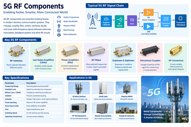
Amplifiers, filters, switches, power dividers, couplers, and antennas are combined to support signal transmission, base station testing, and wireless infrastructure.
RF power amplifiers generate high transmit power, while low-noise amplifiers improve receiver sensitivity. Passive switches and waveguide components route high-frequency signals.
Low-noise active front ends work together with high-performance passive filters, couplers, switches, and waveguide assemblies.
Coaxial switches, attenuators, power dividers, directional couplers, and amplifiers are used to create automated and accurate test systems.
Systems often require components with excellent reliability, wide temperature capability, high isolation, and stable RF performance.
Compact RF integrated circuits and passive matching networks enable wireless communication in space-constrained electronic products.
The correct choice depends on the function required within the RF signal chain. If the system needs to increase signal power, generate a signal, convert frequency, or perform electronically controlled amplification, an active RF component is generally required.
If the system needs to route, filter, split, combine, couple, attenuate, or match an RF signal without providing gain, a passive RF component is typically the appropriate choice.
An RF switch can be either active or passive depending on its technology. Electromechanical coaxial switches are generally considered passive RF components, while PIN diode and semiconductor switches require bias or control power and are commonly classified as active or active-controlled devices.
Yes. RF amplifiers require external power and can provide signal gain, making them active RF components.
Yes. A conventional RF power divider distributes input RF power among multiple output ports without generating additional RF energy.
Yes. Passive components do not generate gain, but insertion loss before an LNA can degrade the overall noise performance of a receiver.
Proper impedance matching minimizes signal reflections and helps maximize power transfer, maintain gain accuracy, improve efficiency, and protect sensitive RF stages.
Understanding the difference between active and passive RF components is fundamental to successful RF and microwave system design. Active components provide functions such as amplification, signal generation, frequency conversion, and electronic control, but they require power and careful consideration of noise, linearity, stability, and thermal performance. Passive components manage RF energy through switching, filtering, coupling, dividing, attenuating, and impedance matching, with key specifications including insertion loss, VSWR, isolation, bandwidth, and power handling. The best RF designs combine both technologies strategically, allowing each component to perform the function for which it is best suited while maintaining the required system performance, reliability, and efficiency.


High-tech Enterprise, Feifeng Talent
Chief Engineer Wang graduated with a master's degree in high-power microwave from the Institute of Electronics, University of Chinese Academy of Sciences.
View Full Profile