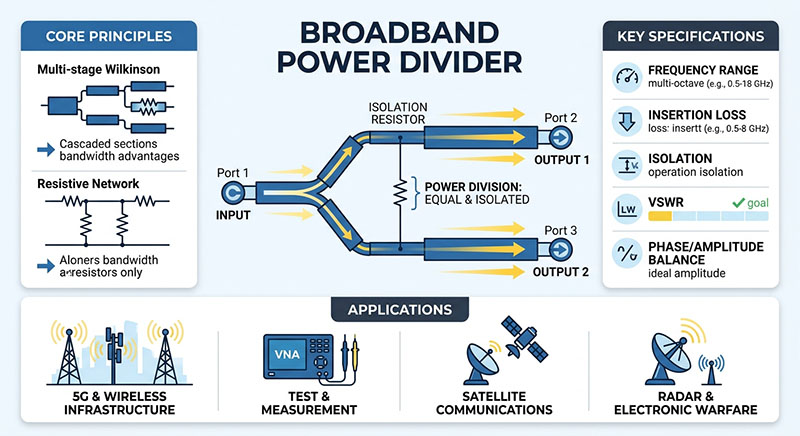
Broadband power dividers are fundamental RF and microwave components used to split an input signal into two or more output paths while maintaining predictable amplitude, phase, impedance, and isolation characteristics. At frequencies extending from DC to 67 GHz, achieving consistent performance across the entire bandwidth becomes significantly more challenging.
For advanced applications such as 5G/6G testing, aerospace and defense, radar, satellite communications, semiconductor test equipment, and high-speed RF instrumentation, simply specifying a power divider by frequency range is not enough. Engineers must also evaluate amplitude balance, phase balance, insertion loss, return loss, isolation, power handling, and connector performance.
What Is a Broadband Power Divider?
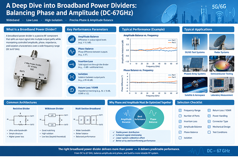
A broadband power divider is a passive RF component that distributes an input signal into multiple output ports over a wide frequency range. Depending on its architecture, a divider can provide equal or unequal power division while maintaining a controlled impedance, commonly 50 ohms in RF systems.
For an ideal two-way equal power divider, the input signal is divided equally between two output ports. The theoretical power split is:
Ideal two-way division loss = 10 log10(2) ≈ 3.01 dB
The practical insertion loss is higher because of conductor loss, dielectric loss, mismatch, coupling structures, connectors, and other implementation effects.
A broadband design must maintain acceptable electrical performance over a very large frequency range rather than being optimized around a narrow center frequency. This makes DC-67GHz power divider design particularly demanding.
Why DC-67GHz Broadband Operation Is Challenging
Moving from conventional microwave frequencies toward millimeter-wave frequencies introduces additional electrical and mechanical constraints. At 67 GHz, small changes in geometry can produce measurable changes in RF performance.
Transmission-Line Loss
Conductor and dielectric losses generally become more significant as frequency increases. Surface roughness and conductor geometry can also influence insertion loss.
Connector Effects
At 67 GHz, connector interfaces become a critical part of the RF path. Connector design, repeatability, alignment, and mating quality can affect return loss and insertion loss.
Electrical Length
A small physical length corresponds to a meaningful electrical phase shift at millimeter-wave frequencies. Manufacturing tolerances can therefore affect phase balance.
Wideband Matching
Maintaining low reflection across several decades of frequency requires careful impedance control and broadband circuit architecture.
Amplitude Balance: Keeping Output Power Consistent
Amplitude balance describes how closely the output signal levels match each other. For a two-way equal power divider, ideal outputs have identical power levels.
For example, suppose an input signal is divided into two output paths. If one output has an insertion loss of 3.4 dB and the other has an insertion loss of 3.7 dB, the amplitude imbalance is approximately:
Amplitude imbalance = |3.7 − 3.4| = 0.3 dB
A low amplitude imbalance is important when the outputs feed parallel signal-processing chains, phased-array elements, mixers, amplifiers, or measurement channels.
Why Amplitude Balance Matters
-
Maintains consistent signal power between parallel RF paths.
-
Improves channel-to-channel measurement repeatability.
-
Helps maintain uniform excitation in antenna arrays.
-
Reduces calibration requirements in multi-channel systems.
-
Supports predictable performance in coherent RF architectures.
Amplitude balance should always be evaluated across the complete operating bandwidth rather than at only one frequency.
Phase Balance: The Other Half of Broadband Performance
Phase balance represents the phase difference between the output ports relative to the expected phase relationship. In a conventional equal two-way divider, engineers may require the output phases to remain closely matched across the operating frequency range.
Phase balance becomes particularly important in systems where multiple RF signals are recombined or used coherently.
Applications Sensitive to Phase Balance
-
Phased-array antennas
-
Beamforming networks
-
Radar front ends
-
Vector network analyzer test systems
-
Coherent signal processing
-
5G and emerging 6G test platforms
-
Electronic warfare and direction-finding systems
-
Multi-channel transceiver architectures
Even when amplitude balance is excellent, phase imbalance can cause errors when signals are combined. Therefore, broadband power-divider selection should consider amplitude and phase specifications together.
Amplitude Balance vs. Phase Balance
|
Parameter
|
What It Describes
|
Why It Matters
|
Typical Sensitive Applications
|
|
Amplitude Balance
|
Difference in output signal magnitude
|
Ensures consistent power distribution
|
Multi-channel RF systems, testing, antenna arrays
|
|
Phase Balance
|
Difference in output phase
|
Maintains coherent signal relationships
|
Beamforming, radar, phased arrays
|
|
Insertion Loss
|
Total signal loss through the divider
|
Determines available output power
|
All RF systems
|
|
Isolation
|
Coupling between output ports
|
Reduces unwanted interaction between channels
|
Amplifier chains, test systems, transceivers
|
|
Return Loss
|
Input/output impedance matching
|
Reduces reflections and VSWR
|
High-frequency and precision RF systems
|
Insertion Loss in Broadband Power Dividers
Insertion loss is one of the most important specifications when evaluating an RF power divider.
For an ideal two-way equal divider, the theoretical division loss is approximately 3.01 dB. A real component will exhibit additional loss caused by its physical construction and materials.
Important: A specification of “3 dB power divider” generally refers to the nominal power split, not necessarily a measured insertion loss of exactly 3.00 dB. Always check the manufacturer's insertion-loss specification and test conditions.
For broadband DC-67GHz operation, insertion loss should ideally be reviewed as a frequency-dependent curve. A divider that performs well at 10 GHz may exhibit significantly different characteristics at 50 or 67 GHz.
Isolation Between Output Ports
Isolation describes how effectively the output ports are electrically separated from one another. High isolation reduces the amount of signal traveling from one output port into another.
This characteristic is especially important when the output ports connect to different active circuits. For example, if one output feeds a high-gain amplifier and another connects to a sensitive receiver, insufficient isolation can allow unwanted signal interaction.
In practical RF systems, isolation can affect:
-
Channel-to-channel interference
-
Amplifier stability
-
Measurement accuracy
-
Signal leakage
-
System calibration
-
Overall RF network performance
Return Loss and VSWR
Return loss indicates how well the RF ports are matched to the system impedance. A higher return-loss value generally corresponds to a lower reflected signal under the same reference conditions.
VSWR provides another way to describe impedance mismatch. The relationship between reflection coefficient magnitude and VSWR is:
VSWR = (1 + |Γ|) / (1 − |Γ|)
where Γ is the magnitude of the voltage reflection coefficient.
For a DC-67GHz power divider, input and output return loss should be evaluated across the entire operating band. This is particularly important near the upper frequency limit, where connectors, transitions, and small dimensional variations can have a greater influence.
Power Divider Architectures
Resistive Power Dividers
Resistive dividers use resistive networks to distribute RF power. They can provide very broad frequency coverage and relatively simple construction.
However, resistive structures dissipate a portion of the input power as heat. They may therefore have lower power-handling efficiency than some transmission-line-based alternatives.
Wilkinson Power Dividers
The Wilkinson power divider is a widely used architecture that can provide good matching and output isolation while maintaining relatively low loss beyond the theoretical power-division loss.
Conventional Wilkinson designs are often associated with specific frequency ranges, but broadband implementations can use multi-section structures and other techniques to extend bandwidth.
Multi-Section Broadband Dividers
Multi-section structures use multiple impedance-transforming sections to improve bandwidth. This approach can provide a useful balance between matching, insertion loss, amplitude balance, and phase performance.
For applications requiring operation from DC or near-DC frequencies through tens of gigahertz, designers may use specialized broadband architectures rather than a conventional narrowband divider.
Why Phase and Amplitude Must Be Optimized Together
One of the central challenges in broadband RF design is that improving one parameter does not automatically improve every other parameter.
A design may achieve excellent amplitude balance while exhibiting a larger phase imbalance. Another design may have excellent phase tracking but higher insertion loss near the top of the frequency range.
Therefore, power-divider optimization is usually a multi-variable engineering problem involving:
-
Amplitude balance
-
Phase balance
-
Insertion loss
-
Return loss
-
Isolation
-
Power handling
-
Bandwidth
-
Connector technology
-
Mechanical repeatability
DC-67GHz Power Divider Connector Considerations
At frequencies approaching 67 GHz, the connector is not simply a mechanical interface. It becomes an important part of the RF transmission path.
Common high-frequency connector technologies include precision coaxial interfaces designed for millimeter-wave operation. Depending on the exact frequency range and application, engineers may encounter 2.92 mm, 2.4 mm, 1.85 mm, or other precision interfaces.
Design consideration: Always verify the connector's actual rated frequency, mating interface, torque requirements, cable compatibility, and measurement repeatability rather than selecting a connector based only on physical appearance.
How to Select a DC-67GHz Broadband Power Divider
Selecting a broadband power divider requires matching the component's electrical specifications with the requirements of the complete RF system.
1. Define the Frequency Range
Determine whether the application actually requires operation from DC through 67 GHz or whether a narrower range is sufficient. A component optimized for a narrower band may offer different performance characteristics.
2. Determine the Number of Output Ports
Common configurations include two-way, three-way, four-way, six-way, and higher-order power dividers. Increasing the number of outputs changes the theoretical division loss and can affect overall insertion loss and physical complexity.
3. Check Amplitude Balance
Review the maximum amplitude imbalance across the complete operating range. For precision multi-channel systems, this parameter may be more important than nominal insertion loss at a single frequency.
4. Check Phase Balance
For coherent applications, examine the phase-balance specification and determine whether it remains acceptable across the complete bandwidth.
5. Evaluate Insertion Loss
Compare measured or guaranteed insertion loss rather than relying only on the nominal division ratio.
6. Evaluate Isolation
If the outputs feed independent RF circuits, verify that the output-to-output isolation is sufficient for the application.
7. Check Return Loss and VSWR
Low reflection is important for maintaining predictable system impedance and minimizing unwanted standing-wave effects.
8. Verify Power Handling
Check average power, peak power, frequency-dependent limitations, temperature conditions, and connector limitations. Do not assume that a broadband divider rated for a certain frequency can automatically handle the same power across its entire band.
9. Confirm Mechanical Requirements
For laboratory and production applications, consider package dimensions, mounting configuration, connector orientation, cable clearance, and mechanical repeatability.
Typical Applications of Broadband DC-67GHz Power Dividers
5G and 6G Test Systems
Broadband dividers can distribute RF signals to multiple test channels, measurement instruments, or device-under-test paths.
Radar Systems
Phase and amplitude consistency are important when multiple coherent RF paths are used for radar signal generation and analysis.
Phased-Array Systems
Power dividers can distribute excitation signals across multiple antenna or transceiver channels.
RF Semiconductor Testing
Broadband components support automated test equipment covering multiple frequency bands and device technologies.
Satellite and Aerospace Electronics
Compact broadband RF components can be integrated into communication and instrumentation architectures where wide frequency coverage is required.
Laboratory Measurement
Network analyzers, signal generators, spectrum analyzers, and RF test fixtures frequently use power dividers for signal distribution and measurement.
Broadband Power Divider Testing
A vector network analyzer is commonly used to characterize broadband power-divider performance. A complete characterization may include measurements of S-parameters over the specified frequency range.
Important measurements include:
-
S11: Input return loss or reflection behavior.
-
S21: Transmission from the input port to one output.
-
S31: Transmission from the input port to another output.
-
S23: Coupling or isolation relationship between output ports.
Amplitude balance can be calculated by comparing the relevant transmission magnitudes, while phase balance can be determined from the corresponding transmission-phase measurements.
Amplitude Balance = |S21,dB − S31,dB|
The exact definition and sign convention should follow the manufacturer's datasheet and measurement methodology.
Measurement Challenges at 67GHz
Measurements at 67 GHz require careful calibration and fixture management. Cable movement, connector repeatability, calibration quality, and environmental conditions can all influence measured results.
Engineers should pay particular attention to:
-
VNA calibration method
-
Calibration reference plane
-
High-frequency cable stability
-
Connector cleanliness
-
Connector mating torque
-
Adapter repeatability
-
Temperature stability
-
Fixture and cable phase stability
At millimeter-wave frequencies, measurement uncertainty should be considered when comparing components from different manufacturers.
Common Mistakes When Choosing a Broadband Power Divider
Focusing Only on Frequency Range
A component labeled “DC-67GHz” may satisfy the frequency requirement while still having unsuitable amplitude balance, phase balance, insertion loss, or isolation for a particular system.
Ignoring Connector Performance
At high frequencies, the connector and transition can contribute significantly to the measured RF response.
Comparing Specifications at Different Test Conditions
Two products should not be compared directly unless their frequency ranges, impedance, temperature, power levels, connector configurations, and measurement conditions are understood.
Using Nominal 3 dB as the Complete Loss Specification
The 3.01 dB theoretical split for an ideal two-way divider does not represent all practical losses.
Overlooking Phase Balance
For coherent RF applications, amplitude balance alone does not provide enough information to determine whether a divider will perform correctly in the system.
Broadband Power Divider Specification Checklist
|
Specification
|
Key Question
|
|
Frequency Range
|
Does the divider cover the complete required operating band?
|
|
Impedance
|
Is the divider compatible with the system impedance, typically 50 Ω?
|
|
Power Division
|
Is equal or unequal power distribution required?
|
|
Insertion Loss
|
How much additional loss exists beyond theoretical division loss?
|
|
Amplitude Balance
|
How closely do the output amplitudes track across frequency?
|
|
Phase Balance
|
How closely do the output phases track across frequency?
|
|
Isolation
|
How effectively are the output ports isolated?
|
|
Return Loss / VSWR
|
How well are the ports impedance matched?
|
|
Power Handling
|
Can the component withstand the required RF power?
|
|
Connector
|
Is the connector appropriate for operation up to 67 GHz?
|
|
Mechanical Design
|
Does the package meet installation and test requirements?
|
Future Trends in Broadband RF Power Distribution
As RF systems move toward wider bandwidths and higher carrier frequencies, broadband power distribution continues to become more important. Advanced test systems increasingly need components capable of covering multiple wireless and microwave bands with consistent electrical characteristics.
The expansion of millimeter-wave communications, high-resolution radar, satellite systems, advanced semiconductor testing, and phased-array architectures is increasing the demand for RF components that provide predictable performance across wide frequency ranges.
For these applications, the key design objective is not simply maximum bandwidth. Instead, engineers need an appropriate balance among bandwidth, amplitude accuracy, phase accuracy, insertion loss, isolation, impedance matching, power handling, and mechanical reliability.
Frequently Asked Questions
What is a broadband power divider?
A broadband power divider is a passive RF component that distributes an input signal among multiple output ports over a wide frequency range while maintaining specified amplitude, phase, impedance, and isolation characteristics.
What is the theoretical loss of a two-way power divider?
The ideal power-division loss of an equal two-way divider is approximately 3.01 dB. Practical insertion loss is normally higher because of component and transmission-line losses.
Why is phase balance important in a power divider?
Phase balance is important when output signals must maintain a predictable phase relationship, particularly in phased arrays, beamforming systems, radar, coherent measurement systems, and multi-channel RF architectures.
What is amplitude balance?
Amplitude balance is the difference between the signal levels at the output ports of a power divider. Lower amplitude imbalance generally means more consistent power distribution between channels.
What should engineers consider when selecting a DC-67GHz power divider?
Important parameters include frequency range, number of ports, insertion loss, amplitude balance, phase balance, isolation, return loss, VSWR, power handling, connector type, mechanical configuration, and measurement conditions.
Why is DC-67GHz operation technically demanding?
The extremely wide bandwidth and high upper frequency increase the influence of transmission-line losses, connector transitions, dimensional tolerances, impedance discontinuities, and manufacturing repeatability.
Conclusion
A broadband power divider covering DC to 67GHz must do more than simply distribute RF power. Its value in a high-performance RF system depends on how consistently it maintains amplitude, phase, impedance matching, isolation, and insertion-loss characteristics throughout the operating bandwidth.
For precision applications, amplitude balance and phase balance should be evaluated together. Engineers should also examine S-parameter data, connector performance, power handling, mechanical construction, and measurement conditions before selecting a component.
Whether used in 5G/6G test equipment, radar, phased-array antennas, aerospace electronics, semiconductor testing, or laboratory instrumentation, a carefully specified broadband power divider can provide the predictable signal distribution required by modern high-frequency RF systems.