
























Directional couplers explained — what they are, how they work, the main types, key specifications, and the most common applications in RF, microwave, and test systems.
Sep 02 ,26


5G communication testing, wireless terminal automated testing
Aerospace communication systems
Precision measurement equipment, radio frequency signal control of radar transmitters
Communication and navigation systems
Optical communication module-related testing
Interconnection of wireless communication base stations
Directional couplers are essential passive RF and microwave components used for signal sampling, power monitoring, measurement systems, and communication networks. They allow engineers to extract a controlled portion of RF power from a transmission line while maintaining signal flow through the main path.
Understanding key parameters such as coupling, directivity, and mainline loss is critical when selecting a directional coupler for applications including wireless communication, radar systems, satellite links, and RF test equipment.

A directional coupler is a four-port passive microwave device that transfers a specific amount of electromagnetic energy between two transmission lines while maintaining isolation between certain ports. It is designed to sample RF signals without significantly affecting the main transmission path.
The four ports of a typical directional coupler include:
Directional couplers are commonly manufactured using microstrip, stripline, waveguide, or coaxial transmission line technologies depending on frequency range and power requirements.
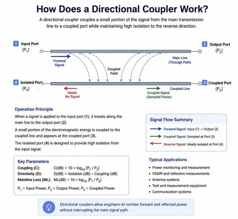
A directional coupler works by using electromagnetic coupling between two closely positioned transmission lines. When an RF signal travels through the main line, a small portion of the energy is transferred to the secondary coupling line.
The coupling structure is designed so that the coupled signal appears mainly at one output port while minimizing unwanted signal leakage at the isolated port. This directional behavior allows engineers to measure forward and reflected power separately.
The performance of a directional coupler depends primarily on coupling factor, directivity, insertion loss, return loss, frequency range, and power handling capability.
Coupling is one of the most important specifications of a directional coupler. It represents the ratio between the input power and the power available at the coupled port.
The coupling factor is expressed in decibels (dB) and is calculated as:
Coupling (dB) = 10 × log10(Input Power / Coupled Power)
For example, a 10 dB directional coupler means that approximately 10% of the input power is available at the coupled port, while most of the signal continues through the main line.
| Coupling Value | Typical Application |
|---|---|
| 3 dB | Power splitting and balanced systems |
| 10 dB | RF monitoring and measurement |
| 20 dB | High-power signal sampling |
| 30 dB | Precision measurement systems |
Directivity describes how effectively a directional coupler separates forward and reverse signals. It is a measurement of isolation between the coupled port and the unwanted signal direction.
Directivity is calculated as:
Directivity (dB) = Isolation (dB) - Coupling (dB)
A higher directivity value indicates better performance because less unwanted energy reaches the isolated port.
High-performance directional couplers used in vector network analyzers and radar systems often require directivity values above 30 dB.
Mainline loss, also called insertion loss, refers to the amount of signal power lost when the RF signal travels from the input port to the output port.
Ideally, a directional coupler should provide extremely low mainline loss so that the transmitted signal remains strong and efficient.
Low-loss directional couplers are especially important in applications where signal power efficiency is critical, such as satellite communication and high-frequency wireless systems.
| Specification | Description |
|---|---|
| Frequency Range | The operating bandwidth of the coupler. |
| Coupling | The amount of sampled RF power. |
| Directivity | The ability to distinguish signal direction. |
| Insertion Loss | Power loss through the main transmission path. |
| Power Handling | Maximum RF power the device can withstand. |
| VSWR | Indicates impedance matching performance. |
Directional couplers are widely used across RF and microwave industries, including:
Although directional couplers and power dividers both distribute RF energy, they serve different purposes.
Engineers typically use directional couplers for monitoring and measurement, while power dividers are used for signal distribution.
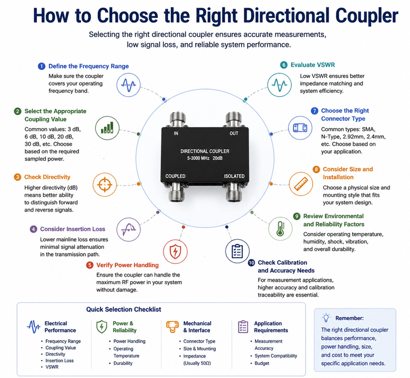
Selecting the correct directional coupler requires evaluating application requirements and system specifications.
Directional couplers play a critical role in modern RF and microwave systems by enabling accurate signal monitoring and power measurement without interrupting the main transmission path.
Understanding coupling, directivity, and mainline loss helps engineers select the right component for applications ranging from wireless networks and radar systems to laboratory testing equipment. High-quality directional couplers provide excellent isolation, low insertion loss, and reliable RF performance across demanding environments.

High-tech Enterprise, Feifeng Talent
Chief Engineer Wang graduated with a master's degree in high-power microwave from the Institute of Electronics, University of Chinese Academy of Sciences.
View Full Profile