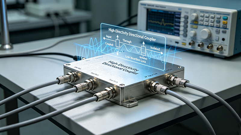
Directional Couplers: Their Operation and Application
Directional couplers are passive RF components that sample a defined fraction of a signal traveling in one direction along a transmission line while isolating the opposite direction. They are fundamental to RF power measurement, VSWR monitoring, signal sampling, feedback control, and test-and-measurement systems.
Quick Answer
A directional coupler is a four-port device with input, output, coupled, and isolated ports. Power entering the input is split: most continues to the output, while a known fraction appears at the coupled port. Power traveling in the reverse direction ideally exits at the isolated port and not at the coupled port. By combining two couplers back-to-back, a dual directional coupler simultaneously measures forward and reflected power — the basis of VSWR and return-loss measurement.
What Is a Directional Coupler?
A directional coupler is a passive RF component that performs signal splitting with directionality. It is described by four ports:
Input (Port 1): the main signal enters here.
Output (Port 2): the main signal exits here with minimal loss.
Coupled (Port 3): a defined fraction of the forward wave appears here.
Isolated (Port 4): ideally zero signal; in practice a small leakage of the reverse wave.
The relationship between the four ports defines the coupler's behavior and is captured in three key parameters: coupling, insertion loss, and directivity.
How a Directional Coupler Works
Directional Coupler — Four-Port Model
Forward power enters Port 1, exits Port 2 mostly intact, and is sampled at Port 3. Reverse power ideally exits at Port 4 (isolated) — directivity measures how well Port 3 rejects this reverse power.
Key Specifications
Specification
Definition
Coupling Factor
Ratio of input to coupled power (e.g., 20 dB, 30 dB)
Tracking between forward/reverse sampled signals (dual couplers)
Amplitude Balance
Tracking of forward/reverse amplitudes (dual couplers)
The relationship between three core metrics is:
Directivity (dB) = Isolation (dB) − Coupling (dB)
Types of Directional Couplers
Waveguide
Waveguide Multi-Hole Coupler
Two parallel waveguides share multiple coupling holes for high directivity. Standard above 2 GHz for radar and satellite systems.
Waveguide
Cross-Guide Coupler
Two waveguides crossing at 90° with coupling apertures. Very high directivity in a compact package.
Coaxial
Coaxial Stripline Coupler
Stripline sections with parallel coupled lines. Broadband, easy to integrate. Common up to 40 GHz.
Coaxial
Coaxial Loop Coupler
Two coaxial lines share a coupling aperture. Very high directivity (40 – 50 dB), broadband, used in precision reflectometry.
Planar
Microstrip Branch-Line Coupler
Quarter-wave branches forming a 90° hybrid. Used in feed-forward amplifiers and balanced topologies.
Planar
Lange Coupler
Interdigitated microstrip lines for tight coupling (3 dB) over wide bandwidth. Common in MMIC design.
Specialty
Resistive / Resistive-Card Coupler
Resistive sheets sample the main-line voltage. Cheap and broadband, but lossy — used for low-power monitoring.
Dual
Dual Directional Coupler
Two single couplers back-to-back, providing simultaneous forward and reflected power samples. Essential for VSWR monitoring.
Single vs. Dual Directional Couplers
Aspect
Single
Dual
Ports
3 (input, output, coupled)
4 (input, output, Fwd, Rev)
Measures
Forward only (or reverse only)
Both forward and reverse
VSWR Monitoring
Not directly
Yes, by comparing forward and reverse
Cost
Lower
Higher
Use Case
Signal sampling, monitoring
Radar ALC, broadcast foldback, TWT protection
Choosing the Right Coupling Factor
The coupling factor sets how much of the main-line power reaches the coupled port:
3 – 10 dB (tight coupling): provides a strong sample for low-noise receivers but reduces main-line power and directivity.
20 dB (medium): standard for instrumentation-grade reflectometry; balances signal level and accuracy.
30 – 40 dB (loose): minimal impact on the main line; suited for monitoring high-power transmitters.
50 – 60 dB (very loose): used when monitoring extremely high power where even a small fraction is large.
Important Trade-offs
Coupling vs. directivity: tighter coupling generally lowers directivity.
Directivity vs. bandwidth: high directivity is harder to maintain over wide bandwidths.
Power handling vs. size: high-power couplers need larger cross-sections and more thermal mass.
Frequency vs. topology: waveguide couplers dominate above ~2 GHz; coaxial dominates lower bands.
Rule of Thumb: Choose a coupling factor that puts the sampled signal at least 20 dB above your detector's noise floor. Lower than that, and you lose measurement dynamic range.
Real-World Applications
1. Forward & Reflected Power Monitoring
The most common use: a dual directional coupler samples forward and reflected power on a transmitter feed line. The ratio gives VSWR or return loss, used for foldback protection and compliance verification.
2. Automatic Level Control (ALC)
The forward-coupled port feeds back into the transmitter's gain-control loop, maintaining constant output power despite supply, temperature, or load variations.
3. Antenna Test & Range Reflectometry
Precision coax couplers (40 – 50 dB directivity) measure antenna return loss with high accuracy across wide bandwidths.
4. Source Pull / Load Pull Measurements
Couplers tap the source and load sides of a device under test so that vector network analyzers can extract impedance information.
5. Radar Systems
Dual directional couplers sample the transmitted pulse and the reflected return, providing both ALC and built-in test capability.
6. Feed-Forward Amplifiers
Two couplers — one at input, one at output — drive a cancellation loop that suppresses intermodulation distortion in power amplifiers.
7. Spectrum Monitoring
A loosely-coupled sample feeds a spectrum analyzer or monitoring receiver without disturbing the main traffic.
8. Cable TV and Broadcast
Directional couplers split and combine signals on multi-tap distribution networks.
Integration Considerations
Place the coupler as close as possible to the point of measurement.
Match the connector type to your transmission line (SMA, N, 7-16, waveguide flange).
Use a load rated for the coupled-port power to absorb any reflection.
For high-power systems, derate CW power by 2× – 3× for reliability.
For dual couplers, match phase and amplitude balance to keep reflectometry accurate.
Common Mistakes
Choosing a low-directivity coupler for VSWR measurement: reflected power leaks into the forward sample and corrupts the reading.
Wrong coupling factor: signal too small → noise-limited; too large → wastes main-line power.
Ignoring load mismatch on the coupled port: reflections here leak back into the main line.
Exceeding power rating: arc damage at the coupling apertures.
Skipping factory calibration data: directivity is not constant across the band; use the manufacturer's data.
Verification & Testing
Measure S-parameters on a calibrated VNA; verify directivity across the band.
Power test at rated CW and peak with the system operating at worst-case VSWR.
Thermal-cycle and verify drift in coupling factor and directivity.
For dual couplers, confirm amplitude and phase balance.
Verify VSWR on all four ports.
Key Takeaways
Directional couplers split a signal with directional awareness.
Directivity, coupling, and insertion loss are the three primary specs.
Dual couplers measure forward and reflected power simultaneously.
Choose coupling factor to put the sampled signal well above the detector noise floor.
Frequently Asked Questions
What is a directional coupler?
A directional coupler is a four-port RF component that samples power traveling in one direction along a transmission line while isolating the opposite direction.
What is directivity?
Directivity (dB) = Isolation − Coupling. It measures how well the coupled port rejects the reverse-traveling wave, enabling accurate forward-power measurement.
What is a dual directional coupler used for?
A dual directional coupler simultaneously samples forward and reflected power. It is the standard building block for VSWR monitoring, ALC loops, and feed-forward amplifiers.
Waveguide or coaxial — which should I use?
Waveguide couplers are preferred above 2 – 3 GHz and at very high power. Coaxial couplers are more convenient, broadband, and easier to install but limited by connectors.
What coupling factor should I choose?
Choose coupling that places the sampled signal 20 dB or more above your detector's noise floor. Common values are 20 dB for instrumentation and 30 – 40 dB for high-power monitoring.
Learn how to select high-directivity directional couplers for high-power microwave systems. This guide covers directivity, coupling, isolation, power handling, thermal management, and design trade-offs.
Directional couplers are essential passive RF and microwave components used for signal sampling, power monitoring, measurement systems, and communication networks.
Jul 29 ,26
About the Author — MeiXun Team
Wang
Chief Engineer Wang
High-tech Enterprise, Feifeng Talent
Chief Engineer Wang graduated with a master's degree in high-power microwave from the Institute of Electronics, University of Chinese Academy of Sciences.
View Full Profile
Wang
Chief Engineer Wang
High-tech Enterprise, Feifeng Talent
Chief Engineer Wang graduated with a master's degree in high-power microwave from the Institute of Electronics, University of Chinese Academy of Sciences.
In the same year, he joined CETC 40/41 for work and study. He has been committed to the design and development of microwave switches for a long time.
He has applied for 27 patents as the first inventor in the microwave switch field, with 6 authorized invention patents and 14 utility model patents.
The products he developed cover various application platforms such as civilian testing, vehicle-mounted, shipborne, airborne, and missile-borne.