



























Circuit Symbols: The Complete Guide to Schematic Symbols in Electronics
Quick Answer
Circuit symbols are standardized graphical representations of electronic components used in schematics. Two main standards exist: ANSI / IEEE (American, used in North America) and IEC 60617 (international). Most symbols follow similar shapes — a resistor is a zigzag (ANSI) or rectangle (IEC); a capacitor is two parallel lines; an inductor is a series of loops. Knowing the most common 30 – 50 symbols covers 90 % of all schematics.
What Are Circuit Symbols?
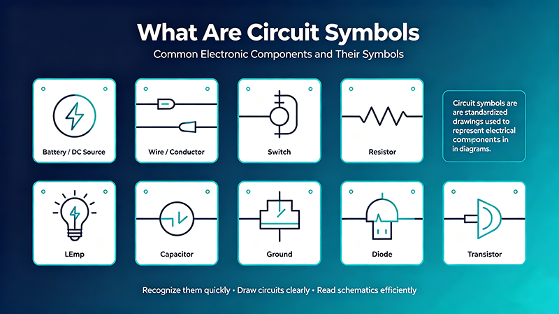
A circuit symbol (or schematic symbol) is a pictogram used to represent an electronic component on a schematic diagram. The lines connecting symbols represent ideal wires, not physical wires. Each symbol conveys:
- The type of component (resistor, diode, IC, etc.).
- Its electrical behavior and any polarity or orientation.
- Sometimes a reference designator (R1, C7, U3) and value (10 kΩ, 100 nF).
Schematics describe how a circuit functions, not how it looks on a PCB. Two different physical layouts can share the same schematic if they are electrically identical.
Standardization: ANSI vs. IEC
| Standard | Region | Common Use |
|---|---|---|
| ANSI / IEEE 315 / 91 | USA, North America | Defense, aerospace, US textbooks |
| IEC 60617 | Europe, Asia, most of world | IEC-compliant schematics |
| JIC | Joint Industry Conference | Older US industrial drawings |
Modern CAD tools (KiCad, Altium, OrCAD) let you select either standard. For international collaboration, IEC is becoming the dominant convention.
Passive Component Symbols
1. Resistor (ANSI / IEC)
The most fundamental component. Both standards exist; the IEC rectangle is more common worldwide.
Semiconductor Symbols
Power & Ground Symbols
- VCC / VDD: arrow pointing up or label "V+" — positive supply rail.
- VEE / VSS: arrow pointing down or label "V−" — negative supply rail.
- Ground (chassis): three horizontal lines, decreasing in width.
- Signal ground: single downward triangle or single line.
- Earth ground: three decreasing lines beneath a vertical line.
Switch & Relay Symbols
- SPST switch: two terminals with an angled line that opens/closes.
- SPDT switch: common terminal + two selectable throws.
- Push-button (momentary): switch with a separate contact bar above.
- Relay coil: rectangular box with multiple pins on one side.
- Relay contact: switch symbol linked to the coil by a dashed line.
Logic Gate Symbols
AND / OR / NOT
AND: D-shape. OR: shield with curved back. NOT: triangle with bubble. Combinations form NAND, NOR, XOR.
Buffer
Triangle with single input and output. Used for signal isolation and line driving.
Flip-Flop
Rectangular block with clock, D, Q, and Q̄ pins. Edge-triggered storage element.
Mux / Demux
Trapezoid with select lines. Routes one of several inputs to a single output (or vice versa).
Source & Meter Symbols
- DC voltage source: circle with + and − inside, or long/short line pair.
- AC voltage source: circle with sine wave inside.
- Battery: multiple long/short line pairs in series.
- Voltmeter (V) / Ammeter (A): circle with letter inside.
- Ground reference: horizontal line with decreasing tiers below.
Reference Designators
| Prefix | Component |
|---|---|
| R | Resistor |
| C | Capacitor |
| L | Inductor |
| D | Diode |
| Q | Transistor (BJT / FET) |
| U | Integrated circuit |
| SW | Switch |
| J | Connector |
| TP | Test point |
| F | Fuse |
| T | Transformer |
How to Read a Schematic
- Identify the power rails first (VCC, GND).
- Trace each functional block: input → processing → output.
- Follow signal flow arrows or wires from left to right.
- Locate key components — ICs, transistors, filters.
- Identify decoupling capacitors near each IC.
- Cross-check reference designators with the BOM.
Common Mistakes
- Mixing ANSI and IEC symbols: confuses readers and CAD libraries.
- Missing polarity marks: polarized capacitors and diodes must show orientation.
- Drawing wires through components: wires should not pass behind symbols.
- Forgetting ground reference: every net must have a defined return path.
- Using wrong reference prefix: "T" for a transistor breaks BOM sorting.
Tools for Drawing Schematics
- KiCad Eeschema: free, open-source, IEC-friendly.
- Altium Designer: industry standard for professional PCB design.
- OrCAD / Cadence: high-end mixed-signal and RF design.
- EasyEDA: free online tool with integrated PCB layout.
- LTspice: free schematic + SPICE simulator, ANSI defaults.
Key Takeaways
- Circuit symbols are a universal language for electronic schematics.
- ANSI and IEC are the two dominant standards.
- Knowing 30 – 50 common symbols covers most schematics.
- Reference designators identify components uniquely.
- Always follow polarity, orientation, and value conventions.
Frequently Asked Questions
What are circuit symbols?
Circuit symbols are standardized graphical icons used on schematics to represent electronic components such as resistors, capacitors, diodes, and transistors.
What is the difference between ANSI and IEC symbols?
ANSI is the American standard (zigzag resistor, etc.). IEC 60617 is the international standard (rectangular resistor). Most modern CAD tools support both.
What is the most common circuit symbol?
The resistor, capacitor, inductor, and diode are the four most-used symbols in any schematic. They appear in nearly every circuit.
Where can I learn schematic symbols?
Textbooks, CAD tutorials (KiCad, Altium), and standards documents (IEEE 315, IEC 60617) all teach symbols. Most university electronics courses start with symbols.
What is a reference designator?
A reference designator is a label like "R1" or "C7" that uniquely identifies a component on a schematic and matches the BOM.
About the Author — MeiXun Team
Chief Engineer Wang
High-tech Enterprise, Feifeng Talent
Chief Engineer Wang graduated with a master's degree in high-power microwave from the Institute of Electronics, University of Chinese Academy of Sciences.
View Full Profile- RF Switch Circuit Diagram
- RF Switch
- Ohm's Law
- dBm to Watt
- mW to dBm
- Wavelength to Frequency
- RF Connector
- SMA Connector
- RF Switch Module
- RF Coupler
- RF PIN Switch
- Microwave Coaxial Switch
- PIN Switch
- Coaxial RF Switch
- Waveguide Switch
- Microwave Switch
- Low Noise Amplifier
- PIN Diode Switch
- Coaxial Switch
- RF Microwave Switch
- SPST Switch