


























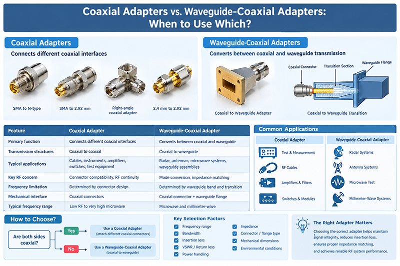
Coaxial adapters and waveguide-coaxial adapters are both used to connect RF and microwave components, but they solve different interconnection problems.
Sep 22 ,26


5G communication testing, wireless terminal automated testing
Aerospace communication systems
Precision measurement equipment, radio frequency signal control of radar transmitters
Communication and navigation systems
Optical communication module-related testing
Interconnection of wireless communication base stations
Learn how waveguide-to-coaxial adapters work, why they are essential in microwave testing, how to select the right adapter, and which specifications matter most for accurate RF and microwave measurements.

A waveguide-to-coaxial adapter, also called a waveguide coax adapter or waveguide-to-coax transition, is a passive microwave component designed to connect two different transmission-line technologies: waveguide and coaxial cable.
Waveguides are widely used at microwave and millimeter-wave frequencies because they can provide low transmission loss, high power handling, and excellent shielding. Coaxial cables, on the other hand, are extremely convenient for connecting laboratory instruments and RF components.
The adapter creates a controlled electromagnetic transition between these two transmission media. A properly designed transition maintains good impedance matching and minimizes insertion loss, return loss, and unwanted electromagnetic radiation across its specified frequency range.
Provides a standardized waveguide interface such as WR-28, WR-42, WR-62, WR-90, or another waveguide designation.
Uses a coaxial connector such as SMA, 2.92 mm, 2.4 mm, 1.85 mm, N-type, or another RF interface.
Converts the electromagnetic mode and field distribution between coaxial transmission and waveguide propagation.
Modern microwave laboratories frequently contain instruments with coaxial RF ports while the device under test uses waveguide interfaces. Without a suitable transition, engineers cannot directly connect the equipment to the DUT.
A high-quality waveguide-to-coaxial adapter provides a practical measurement interface while preserving RF performance. This is particularly important when testing components operating at high microwave and millimeter-wave frequencies.
The fundamental purpose of the adapter is to transform the electromagnetic field distribution from a coaxial transmission line into the appropriate waveguide mode.
In a typical rectangular-waveguide transition, a coaxial probe or similar coupling structure extends into the waveguide. The probe excites the dominant waveguide mode, commonly the TE10 mode in rectangular waveguide systems.
The transition geometry is carefully engineered so that the impedance and electromagnetic field distribution change gradually enough to reduce reflections. Mechanical dimensions, probe position, insertion depth, dielectric materials, conductor geometry, and waveguide dimensions all influence the final RF performance.
Rectangular waveguide adapters are among the most common solutions for microwave laboratory systems. They are available for standardized waveguide sizes including WR-90, WR-62, WR-42, WR-28, WR-22, and many other configurations.
They are commonly used for antennas, filters, radar components, microwave circuits, and test fixtures.
Circular waveguide transitions are used when the application requires circular waveguide propagation. They can be found in specialized antenna systems, radar equipment, satellite communication systems, and high-frequency laboratory setups.
Right-angle configurations change the physical direction of the RF connection. They can simplify mechanical integration where a straight adapter would create space or cable-routing problems.
Inline transitions provide a straight RF path, while end-launch configurations are often designed to integrate with specific waveguide assemblies or test fixtures. The appropriate configuration depends on mechanical constraints and the desired measurement setup.
Waveguide dimensions are closely related to operating frequency. Each standard waveguide has a recommended frequency band in which the desired propagation mode can operate effectively.
For example, commonly encountered designations include WR-90 for X-band applications, WR-62 for higher-frequency microwave systems, WR-42 for Ku-band applications, and WR-28 for Ka-band systems. Exact usable frequency ranges vary according to the specific design and manufacturer.
| Waveguide Example | Typical Frequency Region | Common Applications |
|---|---|---|
| WR-90 | X-band | Radar, antennas, microwave testing |
| WR-62 | Ku-band region | Satellite, radar, RF test systems |
| WR-42 | Ku-band region | Radar, communications, component testing |
| WR-28 | Ka-band region | Satellite, aerospace, millimeter-wave testing |
The frequency ranges above are representative rather than universal specifications. Always verify the manufacturer's specified operating band before selecting an adapter.
The first specification to check is the adapter's frequency range. The adapter should cover the complete measurement band with sufficient margin for the intended application.
Insertion loss represents the amount of signal power lost as the RF signal passes through the adapter. Lower insertion loss is generally preferred because excessive loss can reduce available signal power and affect measurement accuracy.
Return loss indicates how much incident power is reflected by impedance mismatch. VSWR provides another way to characterize the quality of the RF match.
For precision laboratory measurements, a transition with low VSWR and high return loss is desirable because it minimizes reflections between the instrument, adapter, cable, and DUT.
The coaxial connector must match the test equipment and cable assembly. Common choices include SMA, 2.92 mm, 2.4 mm, 1.85 mm, and N-type connectors.
At higher frequencies, connector selection becomes particularly important because mechanical tolerances and connector geometry have a greater impact on RF performance.
If the adapter is used with a high-power amplifier, transmitter, or radar test system, verify its continuous-wave and peak-power capabilities. Thermal management and arcing considerations may also become important at high power.
Check the waveguide flange type, mounting-hole pattern, flange dimensions, connector orientation, and overall envelope. Mechanical incompatibility can make an otherwise suitable adapter unusable.
For vector network analyzer measurements and phased-array applications, phase stability can be just as important as insertion loss. Temperature, mechanical movement, connector repeatability, and construction quality can influence measurement stability.
One of the most important laboratory applications is connecting a vector network analyzer to a waveguide device under test.
A VNA typically provides coaxial test ports, while the DUT may have waveguide ports. The adapter provides the physical and electromagnetic transition required to measure parameters such as S11, S21, insertion loss, return loss, and phase response.
When using a waveguide-to-coaxial adapter in a VNA setup, calibration strategy is critical. The adapter itself introduces loss, reflection, and phase delay, which can become part of the measurement uncertainty if not properly characterized.
Depending on the measurement configuration, engineers may calibrate at the coaxial reference plane and then mathematically de-embed the adapter, or use an appropriate waveguide calibration method to move the measurement reference plane closer to the DUT.
Do not assume that an adapter is electrically transparent simply because its insertion loss is small. Its phase delay, reflection characteristics, connector repeatability, and frequency response can affect high-precision measurements.
Selecting an adapter should be based on both electrical and mechanical requirements. A useful selection process is to evaluate the following factors in order:
Used to connect test instruments to waveguide radar components, antennas, filters, and front-end assemblies.
Supports high-frequency testing of satellite RF and microwave subsystems.
Provides an interface between coaxial measurement equipment and waveguide-fed antenna systems.
Useful for characterizing filters, couplers, transitions, amplifiers, and other microwave components.
High-frequency transitions support component and subsystem evaluation for advanced wireless technologies.
Used in precision microwave test fixtures, radar development, electronic warfare, and communication systems.
In practical RF engineering, the terms waveguide-to-coaxial adapter and coaxial-to-waveguide transition are often used interchangeably. Both describe a component that provides an electromagnetic interface between coaxial and waveguide transmission lines.
The difference is usually descriptive rather than functional. The name may reflect the direction in which the component is being discussed or the interface arrangement specified by the manufacturer.
| Problem | Possible Cause | Recommended Action |
|---|---|---|
| High VSWR | Poor transition matching or connector problem | Inspect interfaces and verify adapter specifications |
| Unexpected insertion loss | Adapter loss, contamination, or poor connection | Clean interfaces and characterize the adapter |
| Unstable measurements | Connector repeatability or mechanical movement | Use proper torque and secure the mechanical assembly |
| Poor high-frequency performance | Connector or adapter bandwidth limitation | Select a transition rated for the required frequency |
Even a high-performance adapter cannot compensate for poor measurement technique. Follow these practices when using waveguide-to-coaxial adapters:
Its primary purpose is to provide a controlled RF transition between a waveguide and a coaxial transmission line, allowing microwave equipment and waveguide components to be connected for testing or system integration.
No. The connector must be compatible with the required frequency range, cable assembly, and test equipment. SMA, 2.92 mm, 2.4 mm, and 1.85 mm connectors are common choices for different microwave and millimeter-wave frequency ranges.
Yes. Every practical transition introduces some loss. A well-designed adapter can minimize insertion loss, but its electrical contribution should still be considered in precision measurements.
The adapter can introduce reflection, insertion loss, and phase delay. These effects can be included in the calibration reference plane or removed through appropriate characterization and de-embedding techniques.
The correct adapter depends on the operating frequency, waveguide standard, coaxial connector, required VSWR, insertion loss, power handling, and measurement accuracy. For millimeter-wave testing, connector bandwidth and mechanical precision become particularly important.
Low VSWR indicates a better impedance match and therefore less reflected power. This helps improve signal transfer and reduces the adapter's impact on RF measurement accuracy.
Waveguide-to-coaxial adapters are essential building blocks for modern microwave and millimeter-wave test systems. They bridge the gap between waveguide-based RF components and coaxial laboratory equipment, making it possible to perform accurate measurements with VNAs, signal generators, spectrum analyzers, power meters, and other instruments.
When selecting a waveguide-to-coaxial adapter, engineers should evaluate frequency range, waveguide standard, coaxial connector, insertion loss, VSWR, power handling, mechanical compatibility, and calibration requirements. For high-frequency and precision applications, connector quality, dimensional accuracy, repeatability, and phase stability should receive particular attention.
By choosing a properly specified transition and following sound RF measurement practices, engineers can minimize measurement uncertainty and obtain reliable performance data from microwave and millimeter-wave devices.
For laboratory testing, aerospace, radar, satellite communication, and other high-frequency applications, choose waveguide-to-coaxial adapters according to the required frequency, waveguide standard, connector interface, RF performance, and mechanical configuration.
Related RF topics: waveguide adapter, waveguide-to-coaxial transition, coaxial waveguide adapter, microwave adapter, RF adapter, millimeter-wave adapter, waveguide testing, VNA measurement, RF test and measurement, microwave components.
High-tech Enterprise, Feifeng Talent
Chief Engineer Wang graduated with a master's degree in high-power microwave from the Institute of Electronics, University of Chinese Academy of Sciences.
View Full Profile