




























Coaxial Cable Switches vs. Transfer Switches –Which One to Choose?
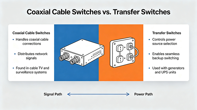
Understanding the Fundamentals
Both coaxial switches and transfer switches are electromechanical or solid-state devices designed to route High Frequency (HF), Very High Frequency (VHF), Ultra High Frequency (UHF), and microwave signals along specified pathways. However, their internal switching topologies dictate fundamentally different application scenarios.
1. Coaxial Cable Switches (Standard SPDT/SPnT)
A standard coaxial switch typically operates in single-pole configurations, such as Single Pole Double Throw (SPDT) or Single Pole N-Throw (SP3T, SP4T, SP6T, etc.). It routes a single input signal to one of multiple output paths, or vice versa.
Port 1 (Common) <--- Switch ---> Port 2 (NC) OR Port 3 (NO)
Key Characteristics:
- Routing Architecture: 1-to-N or N-to-1 switching.
- Termination Options: Available in terminated (absorptive) or open (reflective) configurations. Terminated versions connect unused ports to an internal 50-ohm load to preserve impedance matching.
- Primary Use Case: Selecting between multiple antennas, signal sources, or measurement channels.
2. Coaxial Transfer Switches (DPDT Configuration)
A transfer switch is functionally a Double Pole Double Throw (DPDT) switch with four RF ports configured in a matrix or loop setup. It allows two independent RF signal paths to be switched simultaneously between two different configurations.
Position 1: (Port 1 → Port 2) AND (Port 3 → Port 4)
Position 2: (Port 1 → Port 4) AND (Port 3 → Port 2)
Key Characteristics:
- Routing Architecture: Dual-path simultaneous crossover switching (4-port layout).
- Reversibility: Ideal for inserting/removing a device-under-test (DUT), amplifier, or filter into a transmission line dynamically without physically disconnecting hardware.
- Primary Use Case: Transceiver protection, automated test equipment (ATE) matrices, and signal bypass loops.
Detailed Feature Comparison
To evaluate which component fits your RF front-end design, compare their critical technical parameters in the summary table below:
| Feature / Metric | Coaxial Switch (SPDT / SPnT) | Coaxial Transfer Switch (DPDT) |
|---|---|---|
| Port Count | 3 ports (SPDT) up to 12+ ports (SP12T) | 4 RF ports standard |
| Switching Topology | Single input to multiple outputs (or vice versa) | Simultaneous dual-channel path reversal |
| Bypass Capability | Requires multiple SPDT switches to implement bypass | Inherent single-component bypass functionality |
| Insertion Loss | Generally lower per channel due to simpler RF paths | Slightly higher due to internal crossover architecture |
| Isolation | High isolation between selected and unselected ports | High isolation between both active transmission paths |
| System Complexity | Simpler control logic (1 actuator or bit per path) | Requires synchronized drive mechanism for dual paths |
When to Choose a Standard Coaxial Switch
A standard coaxial switch (SPDT, SP3T, SP4T, etc.) is the most cost-effective and straightforward choice under the following conditions:
- Multi-Antenna Selection: When a single radio transmitter/receiver needs to switch between directional, omnidirectional, or multi-band antennas.
- RF Test Bench Distribution: When multiplexing a single Spectrum Analyzer or Vector Network Analyzer (VNA) input across multiple test points.
- Low-Loss Requirements: When minimizing inline attenuation is the highest priority, as SPDT switches generally offer direct, low-loss transmission paths.
When to Choose a Coaxial Transfer Switch
A transfer switch provides distinct performance and operational advantages in advanced RF system architectures:
- Component Bypass Loops: When you need to insert an Low-Noise Amplifier (LNA), Power Amplifier (PA), or attenuator into an active line and bypass it instantly when not needed.
- Transmit/Receive (T/R) Matrix Redundancy: In satellite communications and military radars, transfer switches provide dynamic crossover redundancy, allowing a primary transceiver to fall back seamlessly to a backup unit.
- Calibration & Measurement Switching: Ideal for switching standard reference sources into a measurement path while redirecting the active line to a load, ensuring signal continuity without open-circuit reflections.
Selection Rule of Thumb
Choose SPDT/SPnT Coaxial Switches if your objective is selecting one path out of many. Choose a Transfer Switch if you need to interchange two distinct RF paths or create a fail-safe bypass loop with minimal component count.
Key Technical Factors to Consider Before Buying
Regardless of whether you choose a coaxial switch or a transfer switch, ensure the specification sheet meets your environmental and electrical requirements:
- Frequency Range: Verify bandwidth coverage from DC up to 18 GHz, 26.5 GHz, 40 GHz, or 67 GHz depending on your operational band (Ka-band, Ku-band, millimeter wave).
- Actuator Type: Select between Failsafe (returns to default port upon power loss), Latching (maintains state without power, reducing thermal heat load), or Normally Open.
- Power Handling: Ensure both CW (Continuous Wave) and peak RF power handling limits meet your transmitter output levels.
- Connector Style: Match SMA, 2.92mm, 2.4mm, N-type, or TNC interfaces to prevent impedance mismatches and excessive return loss.
Need Help Selecting the Right RF Switch Topology?
Consult our RF application engineering team today to review S-parameter data, power handling specs, and custom switching matrix configurations tailored to your system architecture.
About the Author — MeiXun Team
Chief Engineer Wang
High-tech Enterprise, Feifeng Talent
Chief Engineer Wang graduated with a master's degree in high-power microwave from the Institute of Electronics, University of Chinese Academy of Sciences.
View Full Profile- RF Switch Circuit Diagram
- RF Switch
- Ohm's Law
- dBm to Watt
- mW to dBm
- Wavelength to Frequency
- RF Connector
- SMA Connector
- RF Switch Module
- RF Coupler
- RF PIN Switch
- Microwave Coaxial Switch
- PIN Switch
- Coaxial RF Switch
- Waveguide Switch
- Microwave Switch
- Low Noise Amplifier
- PIN Diode Switch
- Coaxial Switch
- RF Microwave Switch
- SPST Switch