



























SPDT vs. DPDT Electromechanical Switches: Key Differences and Selection Guide
Table of Contents
- 1. What Is an Electromechanical RF Switch?
- 2. SPDT Electromechanical Switch
- 3. DPDT Electromechanical Switch
- 4. Head-to-Head Specification Comparison
- 5. Latching vs. Failsafe Modes
- 6. Typical Applications
- 7. Selection Decision Framework
- 8. Common Pitfalls to Avoid
- 9. Frequently Asked Questions
- 10. Conclusion
1. What Is an Electromechanical RF Switch?

An electromechanical RF switch uses a magnetic actuator (latching relay or solenoid) to physically move a conductive contact between positions. Because the signal passes through a metal-on-metal contact, insertion loss is extremely low and isolation is exceptionally high — even at millimeter-wave frequencies.
EM switches are characterized by:
- Insertion loss as low as 0.15 dB at 18 GHz
- Isolation exceeding 80 dB at low GHz
- Cycle life of 2–10 million operations
- Switching speed of 10–25 milliseconds
- Power handling up to several hundred watts CW
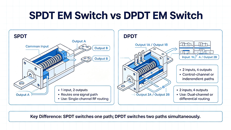
The two dominant topologies are SPDT (single path, two outputs) and DPDT (two paths, two outputs each, switched together).
2. SPDT Electromechanical Switch
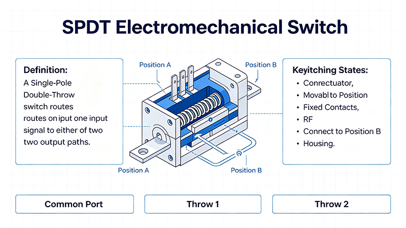
2.1 Architecture
An SPDT EM switch has one input port and two output ports (A and B). A single magnetic actuator drives a contact between the input and either output. Most designs are self-terminating: when the contact moves, the previously connected output is internally terminated with 50 Ω to absorb residual energy.
2.2 Strengths
- Lowest insertion loss and cost
- Compact size, lighter weight
- Wide variety of connector options
- Excellent for high-cycle ATE use
2.3 Limitations
- Cannot reverse signal direction by itself
- Only one signal path can be controlled
- Two SPDTs needed to replicate DPDT functionality
3. DPDT Electromechanical Switch
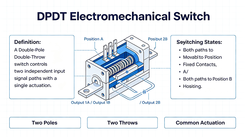
3.1 Architecture
A DPDT EM switch contains two ganged SPDT poles mechanically linked to a single actuator. Both poles switch simultaneously, providing synchronized routing of two independent signal paths — ideal for transmit/receive switching, signal reversal, or differential routing.
3.2 Strengths
- Switches two paths with one control line
- Saves PCB space vs. two discrete SPDTs
- Synchronized switching eliminates timing skew
- Ideal for T/R duplexing and signal reversal
3.3 Limitations
- Higher cost (typically 1.8–2.5× SPDT)
- Larger and heavier
- Slightly higher insertion loss
- More complex internal mechanics
4. Head-to-Head Specification Comparison
| Parameter | SPDT EM Switch | DPDT EM Switch |
|---|---|---|
| Port count | 3 (1 input, 2 output) | 6 (2 inputs, 4 outputs) |
| Insertion loss @ 6 GHz | 0.15–0.30 dB | 0.25–0.45 dB |
| Insertion loss @ 18 GHz | 0.30–0.50 dB | 0.40–0.70 dB |
| Isolation @ 6 GHz | 80–90 dB | 70–85 dB |
| Switching speed | 10–20 ms | 15–25 ms |
| Cycle life | 5–10 million | 2–5 million |
| Power handling | Up to 700 W CW | Up to 500 W CW |
| Self-terminating | Optional | Optional |
| Voltage / Current | 12 V / 24 V / 28 V coil | 12 V / 24 V / 28 V coil |
| Cost (relative) | 1× | 1.8–2.5× |
| Footprint | Smaller | Larger |
5. Latching vs. Failsafe Modes
Latching (Self-Holding)
Uses a magnetic latching relay. A brief pulse of current sets or resets the position. No continuous power is needed — the switch holds its last state when power is removed. Ideal for power-sensitive and remote installations.
- Very low power consumption
- Retains state during power loss
- Requires SET and RESET pulse drivers
- Cycle life: 5–10 million
Failsafe
Uses a spring-return actuator. When power is removed, the switch automatically returns to a default (fail-safe) position. Essential for safety-critical systems where loss of power must not leave the system in an unsafe state.
- Returns to default without external command
- Continuous current required to hold non-default state
- Critical for T/R protection and emergency routing
- Cycle life: 2–5 million
6. Typical Applications
6.1 SPDT Use Cases
- Antenna selection between two radiators
- DUT vs. bypass path in ATE systems
- Redundant instrument routing
- Band-select filter switching
- Source/load selection in production test
6.2 DPDT Use Cases
- Transmit/Receive (T/R) duplexing in radar and radios
- Signal-flow reversal in a test loop
- Differential pair routing
- Cross-connect switching in matrix networks
- Two-channel simultaneous redundancy transfer
7. Selection Decision Framework
Path Count
One path → SPDT. Two paths → DPDT.
Direction
Need reversal? Use DPDT.
Frequency
Verify > 18 GHz availability.
Power
Match CW and peak rating.
Lifecycle
Track cycles vs. life spec.
- Do you need to switch one path or two? One → SPDT. Two synchronized → DPDT.
- Is signal reversal required? Yes → DPDT.
- Is PCB space critical? Yes → SPDT.
- Is cost the dominant constraint? Yes → SPDT.
- Do you need independent control of two paths? Yes → two SPDTs (not ganged DPDT).
- Latching or failsafe? Latching for power-sensitive; failsafe for safety-critical.
8. Common Pitfalls to Avoid
- Hot-switching: Toggling under RF power welds contacts. Always sequence RF off before switching.
- Unterminated unused ports: Use self-terminating models or external 50 Ω terminations.
- Driver undercurrent: Coil voltage and current must meet spec; weak drivers cause missed actuations.
- Connector over-torque: Use a calibrated wrench (8 in-lbs for SMA, 12 in-lbs for Type-N).
- Ignoring cycle count: Track cycles and plan replacement before life spec is exhausted.
- Wrong coil voltage: Verify 12 V vs. 24 V vs. 28 V coil variants match your driver board.
- Mismatched connector gender: Confirm male/female pin configurations to avoid cable rework.
9. Frequently Asked Questions
Q1: Can a DPDT switch be used as two independent SPDT switches?
Only if the switch supports independent pole control. A ganged DPDT toggles both poles simultaneously — which is not equivalent to two independent SPDTs.
Q2: Why are electromechanical switches more expensive than solid-state?
EM switches contain precision mechanical parts, magnetic actuators, and tight-tolerance RF contacts. Solid-state switches use semiconductor dies that scale cheaply in volume.
Q3: Are EM switches suitable for outdoor or rugged environments?
Yes — many EM switches carry MIL-STD-202 ratings for shock, vibration, humidity, and temperature. Confirm the specific environmental ratings with the supplier.
Q4: What is the best connector type for an EM switch?
SMA is most common up to 18 GHz. Type-N is preferred for high-power low-frequency use. For mmWave, use 2.92 mm or 2.4 mm connectors.
Q5: How do I extend EM switch life?
Avoid hot-switching, keep currents within spec, and operate within temperature limits. Use latching modes to reduce continuous power dissipation.
Q6: Can EM switches operate in vacuum?
Most standard EM switches are not vacuum-rated. Specialized space-qualified EM switches exist for satellite applications — consult the supplier for VACMIL-spec options.
10. Conclusion
Both SPDT and DPDT electromechanical switches deliver best-in-class insertion loss, isolation, and power handling for high-frequency RF systems. SPDT is the workhorse default — simple, low cost, and ideal for single-path selection. DPDT shines when you need synchronized dual-path routing, signal reversal, or T/R duplexing. Match the topology to your path-count requirement, choose the right latching vs. failsafe mode, and avoid the common pitfalls above to ensure years of reliable service.
About the Author — MeiXun Team
Chief Engineer Wang
High-tech Enterprise, Feifeng Talent
Chief Engineer Wang graduated with a master's degree in high-power microwave from the Institute of Electronics, University of Chinese Academy of Sciences.
View Full Profile- RF Switch Circuit Diagram
- RF Switch
- Ohm's Law
- dBm to Watt
- mW to dBm
- Wavelength to Frequency
- RF Connector
- SMA Connector
- RF Switch Module
- RF Coupler
- RF PIN Switch
- Microwave Coaxial Switch
- PIN Switch
- Coaxial RF Switch
- Waveguide Switch
- Microwave Switch
- Low Noise Amplifier
- PIN Diode Switch
- Coaxial Switch
- RF Microwave Switch
- SPST Switch