

























Directional couplers explained — what they are, how they work, the main types, key specifications, and the most common applications in RF, microwave, and test systems.
Sep 02 ,26


5G communication testing, wireless terminal automated testing
Aerospace communication systems
Precision measurement equipment, radio frequency signal control of radar transmitters
Communication and navigation systems
Optical communication module-related testing
Interconnection of wireless communication base stations
In RF and microwave systems, a coupler is an important passive component used to sample, divide, combine, monitor, or distribute electromagnetic signals. RF couplers are widely used in communication systems, radar, satellite equipment, test instruments, wireless infrastructure, and microwave measurement applications.
The main functions of a coupler depend on its design and application. A directional coupler, for example, can sample a precisely controlled portion of power traveling through a transmission line while minimizing interference with the main signal. Other coupler configurations can divide power between multiple paths or combine signals from different sources.
This article explains the main functions of a coupler, how RF and microwave couplers work, their key performance parameters, common types, and how to select the right coupler for a specific application.
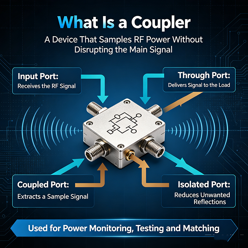
An RF or microwave coupler is a passive device that transfers a defined amount of electromagnetic energy from one transmission path to another. Depending on the design, the coupler may have three, four, or more ports.
Unlike an active component, a passive coupler does not require an external power supply to perform its basic signal-routing function. Instead, it uses electromagnetic coupling between transmission lines, waveguide structures, transformers, or other RF structures.
In simple terms: a coupler allows engineers to access, measure, divide, combine, or monitor RF power without necessarily interrupting the main signal path.
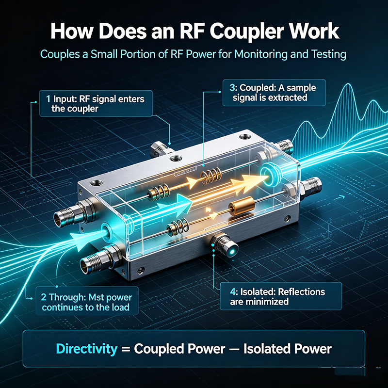
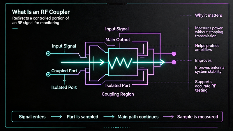
The operating principle of an RF coupler is based on the controlled transfer of electromagnetic energy. When an RF signal enters the input port, most or part of the signal travels along the main transmission path. A specified portion of the energy is coupled into another port.
For a typical directional coupler, the ports may include:
The coupling level is usually expressed in decibels. For example, a 10 dB coupler transfers approximately 10% of the input power to the coupled port, while a 20 dB coupler samples approximately 1% of the power.
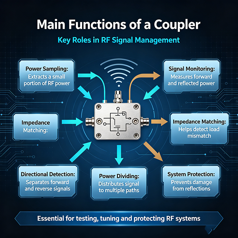
One of the primary functions of a directional coupler is signal sampling. The coupler extracts a small and predictable portion of the power traveling through the main transmission line.
This sampled signal can be sent to measurement instruments, detectors, receivers, spectrum analyzers, or monitoring circuits. The main signal continues toward the load with relatively low disturbance.
Signal sampling is particularly useful when the full RF power level is too high to connect directly to a measurement instrument. A coupler can reduce the sampled power to a safe and measurable level.
RF couplers are commonly used to monitor forward power in transmitters and RF systems. Forward power is the power traveling from the source toward the antenna, load, or next stage of the system.
By connecting a power detector to the coupled port, engineers can continuously monitor the amount of power being transmitted.
Forward power monitoring is important in:
Another important function of a directional coupler is reflected power measurement. Reflected power occurs when the load impedance does not match the characteristic impedance of the transmission line.
A directional coupler can distinguish between signals traveling in opposite directions. This makes it possible to measure both forward and reflected power.
High reflected power may indicate:
By measuring reflected power, engineers can evaluate system performance and identify potential problems before equipment damage occurs.
Because a coupler can measure forward and reflected power, it is widely used to calculate VSWR and return loss.
These parameters provide important information about impedance matching and signal reflections.
The reflection coefficient can be expressed as:
Γ = √(Preflected / Pforward)
The Voltage Standing Wave Ratio is:
VSWR = (1 + |Γ|) / (1 - |Γ|)
A lower VSWR generally indicates better impedance matching and less reflected power.
Another main function of a coupler is power division. Some couplers are designed to split an input signal into two or more output signals with a specific power ratio.
For example, a 3 dB hybrid coupler ideally divides input power equally between two output ports. Other couplers may provide unequal power division ratios depending on the application.
RF power splitting is used in:
Many passive couplers can also be used in reverse to combine RF signals. Instead of dividing one input into multiple outputs, signals entering separate ports can be combined into a common output path.
This function is useful in power amplifier combining, antenna arrays, communication systems, and microwave circuits where multiple RF signals need to be combined efficiently.
The performance of signal combining depends on factors such as phase relationship, frequency, amplitude balance, isolation, and power handling capability.
Isolation is another important function in many coupler designs. Good isolation helps prevent unwanted signals from traveling between ports where they could interfere with system operation.
For example, in a directional coupler, the isolated port should ideally receive very little power when the signal travels in the specified direction.
High isolation can help:
A major advantage of using an RF coupler is that it allows engineers to monitor a live signal without disconnecting the main transmission path.
The coupled port can provide a sample for real-time monitoring while the majority of the signal continues toward the destination.
This function is valuable in systems that require continuous operation, such as communication networks, radar installations, satellite ground stations, and high-power RF transmitters.
High-power RF signals can damage sensitive instruments if connected directly. A coupler can provide a lower-power sample that is suitable for measurement equipment.
For example, a transmitter may operate at hundreds of watts, while a spectrum analyzer or receiver may only tolerate a small input power level. A directional coupler with an appropriate coupling factor can safely reduce the sampled signal level.
Additional attenuation may still be required depending on the power level and instrument specifications.
Couplers are essential components in RF and microwave test systems. They can be used to sample signals for power measurement, frequency analysis, modulation analysis, and network testing.
Common test and measurement applications include:
Different coupler designs are available for different frequency ranges, power levels, bandwidth requirements, and applications.
| Coupler Type | Main Function | Typical Application |
|---|---|---|
| Directional Coupler | Samples power in a specific direction | Forward/reflected power measurement |
| Bidirectional Coupler | Measures power in both directions | VSWR and return loss monitoring |
| Hybrid Coupler | Splits or combines signals | Balanced circuits and power division |
| 3 dB Coupler | Equal power division | Signal splitting and combining |
| Branch-Line Coupler | Power division with phase control | Microwave circuits |
| Waveguide Coupler | Couples microwave energy in waveguide systems | High-frequency and high-power systems |
| Coaxial Directional Coupler | Samples RF power in coaxial systems | RF testing and communication systems |
When selecting an RF coupler, several electrical specifications should be considered.
The coupling factor indicates how much power is transferred from the main line to the coupled port. It is expressed in decibels.
Coupling (dB) = 10 log10(Pinput / Pcoupled)
A lower coupling value means more power is delivered to the coupled port.
Insertion loss describes the amount of power lost in the main transmission path when the coupler is installed. Lower insertion loss is generally desirable because it helps preserve signal power.
Directivity measures the ability of a directional coupler to distinguish between signals traveling in opposite directions. High directivity improves the accuracy of forward and reflected power measurements.
Isolation indicates how effectively unwanted signal transfer between specific ports is prevented. Higher isolation generally helps reduce interference.
The coupler must operate across the required frequency range. Narrowband and broadband couplers are available for different applications.
Maximum power handling is particularly important in high-power RF systems. The coupler must be capable of operating safely at the required average and peak power levels.
A low VSWR indicates good impedance matching. Poor matching can increase reflections and reduce measurement accuracy.
Selecting the correct coupler requires consideration of the system's electrical and mechanical requirements.
Selection tip: For accurate forward and reflected power measurement, prioritize high directivity and stable coupling performance across the operating frequency range. For signal distribution, focus on the required power split, insertion loss, amplitude balance, phase balance, and isolation.
The main functions of a coupler make it useful across a wide range of industries and systems.
Although RF couplers and power dividers can both transfer power between multiple ports, they are designed for different primary purposes.
A directional coupler is typically used to sample a controlled amount of power while allowing most of the signal to continue through the main line. It can also provide directional information for forward and reflected power measurement.
A power divider is primarily designed to distribute input power between multiple output ports according to a defined ratio.
The choice depends on whether the application requires signal sampling and directional measurement or dedicated power distribution.
The main purpose of a directional coupler is to sample a controlled portion of RF or microwave power traveling in a transmission line while allowing most of the signal to continue through the main path.
Yes. A directional or bidirectional coupler can be used to measure reflected power, which helps engineers evaluate impedance matching, VSWR, and return loss.
A 20 dB coupler ideally samples approximately 1% of the input power and leaves most of the power traveling through the main transmission path.
Directivity describes how well a directional coupler distinguishes between signals traveling in opposite directions. Higher directivity generally improves measurement accuracy.
Yes. Depending on the coupler design and operating conditions, many RF couplers can be used in reverse to combine signals as well as divide them.
The main functions of a coupler include sampling RF signals, monitoring forward and reflected power, measuring VSWR and return loss, splitting and combining power, providing isolation, protecting measurement equipment, and supporting RF testing.
RF and microwave couplers are essential components in modern communication, radar, satellite, testing, and high-frequency electronic systems. Choosing the right coupler requires careful consideration of coupling value, frequency range, insertion loss, directivity, isolation, VSWR, and power handling capability.
By selecting a properly specified RF coupler, engineers can improve measurement accuracy, monitor system performance, reduce the risk of equipment damage, and achieve more reliable RF and microwave system operation.

High-tech Enterprise, Feifeng Talent
Chief Engineer Wang graduated with a master's degree in high-power microwave from the Institute of Electronics, University of Chinese Academy of Sciences.
View Full Profile