

























Directional couplers explained — what they are, how they work, the main types, key specifications, and the most common applications in RF, microwave, and test systems.
Sep 02 ,26


5G communication testing, wireless terminal automated testing
Aerospace communication systems
Precision measurement equipment, radio frequency signal control of radar transmitters
Communication and navigation systems
Optical communication module-related testing
Interconnection of wireless communication base stations
Directional coupler vs. tapper comparison: understand their working principles, signal sampling characteristics, advantages, limitations, and applications to choose the right RF and microwave component for your system.
When designing an RF, microwave, wireless communication, testing, or signal monitoring system, engineers often need to extract a small portion of power from a transmission line without significantly disturbing the main signal path. Two common solutions are the directional coupler and the tap coupler, sometimes informally referred to as a tapper.
Although both devices are used to sample or distribute RF power, they are not interchangeable in every application. A directional coupler is designed to provide controlled coupling with directional discrimination, while a tap coupler is generally intended to extract a defined portion of signal power from a main transmission path with less emphasis on directionality.
So, which is better: a directional coupler or a tapper? The answer depends on what you need to measure, monitor, distribute, or protect. This article explains the differences in detail and provides a practical selection guide.

A directional coupler is a passive RF or microwave component that couples a specified portion of electromagnetic energy from a main transmission line to a secondary port. Its defining characteristic is directionality: the component is designed to preferentially sample energy traveling in one direction while minimizing the signal coupled from the opposite direction.
A typical four-port directional coupler includes:
For example, a 20 dB directional coupler ideally delivers approximately 1% of the mainline power to the coupled port, while allowing approximately 99% of the power to continue through the main transmission path, excluding insertion loss.
A tap coupler, sometimes called a signal tap or informally a tapper, is used to extract a portion of power from a main signal path. The sampled signal can then be sent to a monitoring device, receiver, measurement instrument, or secondary distribution path.
Unlike a directional coupler, a tap coupler may not provide strong directional discrimination. Its primary purpose is typically to create a controlled power split or signal sample rather than accurately separate forward and reverse traveling waves.
Depending on the specific design, a tap may be implemented using:
In practical RF systems, the exact meaning of "tapper" can vary by manufacturer or industry. Therefore, engineers should always review the product's datasheet and port specifications before selecting a component.
| Feature | Directional Coupler | Tapper / Tap Coupler |
|---|---|---|
| Primary Function | Samples RF power with directional discrimination | Extracts or splits a portion of signal power |
| Directionality | High or specified directionality | Often lower or not the primary specification |
| Forward/Reverse Measurement | Well suited for measuring forward and reflected power | Generally less suitable for accurate directional measurements |
| Mainline Signal Impact | Usually low insertion loss | Depends on coupling or splitting method |
| Typical Ports | Usually four ports | Configuration varies by design |
| Measurement Applications | Excellent for RF testing and monitoring | Suitable for basic signal monitoring |
| VSWR and Return Loss Analysis | Highly suitable | Limited depending on design |
| System Complexity | More specialized | Often simpler |
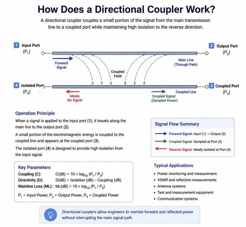
A directional coupler uses electromagnetic coupling between transmission lines or waveguide structures. The geometry and electrical length of the coupling structure are designed so that signals traveling in a specific direction combine constructively at the coupled port and destructively at the isolated port.
The performance of a directional coupler is commonly described using several key parameters:
The coupling factor describes how much power is extracted from the main line. It is expressed in decibels:
Coupling = 10 log10(PInput / PCoupled)
Common coupling values include 3 dB, 6 dB, 10 dB, 20 dB, 30 dB, and 40 dB. A larger coupling value means less power is sampled.
Directivity indicates how effectively the coupler distinguishes between signals traveling in opposite directions. Higher directivity generally improves the accuracy of reflected-power and mismatch measurements.
Insertion loss represents the power lost in the main transmission path. Low insertion loss is important when the system has a limited power budget or requires high signal integrity.
Isolation describes how well unwanted signals are suppressed at the isolated port. High isolation helps reduce measurement errors and unwanted signal interaction.
Directional couplers can separate forward and reflected power, making them valuable for VSWR, return loss, and impedance mismatch analysis.
High-quality couplers can sample a small amount of power while allowing most energy to continue through the main signal path.
They are widely used in communication systems, radar, satellite equipment, RF testing, power monitoring, and laboratory measurement systems.
Properly selected directional couplers can improve the accuracy of power and reflected-signal measurements.
A tap coupler can be an effective choice when the system simply needs to extract a portion of the RF signal for monitoring or distribution.
The main limitation of a tap coupler is that it may not provide the same directional performance as a true directional coupler. If the application requires accurate separation of incident and reflected energy, a basic tap may produce ambiguous or less accurate measurement results.
A tapper may also introduce different levels of:
For simple RF power monitoring, both a directional coupler and a tap coupler may be suitable. However, the best choice depends on whether you need directional information.
A directional coupler is clearly the better choice for VSWR and return loss measurements. These measurements require the system to distinguish between power traveling toward the load and power reflected back from the load.
The reflected power is directly related to impedance mismatch. A directional coupler helps isolate the forward and reverse signal components so that measurement equipment can calculate parameters such as:
For signal distribution, the answer depends on the required power ratio and system architecture.
If you need a specific amount of signal power for a secondary receiver while maintaining the main transmission path, a tap coupler can be a practical solution. If the application also requires directional signal monitoring or isolation between forward and reverse signals, a directional coupler may be preferable.
At microwave and millimeter-wave frequencies, component selection becomes more critical. Small mechanical and electrical variations can significantly affect RF performance.
When selecting either component for high-frequency applications, consider:
For applications extending into the microwave or millimeter-wave spectrum, a professionally designed RF directional coupler with stable frequency performance is often preferred when measurement accuracy is important.
The easiest way to choose is to start with the application's actual technical requirements.
If you must distinguish forward power from reflected power, choose a directional coupler.
Select the required coupling value based on the amount of power needed by the monitoring or measurement equipment.
Verify that the component provides stable performance across the complete operating band.
Check both average and peak power ratings, especially in radar and pulsed RF applications.
Choose a component with sufficiently low mainline insertion loss when preserving signal power is critical.
For precision RF measurements, prioritize directivity, coupling accuracy, repeatability, and frequency stability.
Two components with the same 20 dB coupling value can have very different directivity, insertion loss, power handling, and frequency performance.
RF components are frequency dependent. A coupler optimized for one frequency band may perform poorly outside its specified range.
For reflected-power measurements, insufficient directivity can introduce significant measurement uncertainty.
Unused ports often require proper 50-ohm termination. Incorrect termination can degrade coupling accuracy and isolation.
A simple signal tap may be adequate for monitoring but may not deliver the directional accuracy required for professional RF measurement applications.
| Your Requirement | Recommended Component |
|---|---|
| Measure forward power | Directional Coupler |
| Measure reflected power | Directional Coupler |
| Calculate VSWR | Directional Coupler |
| Measure return loss | Directional Coupler |
| Basic signal monitoring | Tap Coupler or Directional Coupler |
| Extract a signal for a secondary receiver | Tap Coupler |
| High-accuracy RF testing | Directional Coupler |
| Simple power sampling | Tap Coupler |
No. A directional coupler samples or couples power from a main transmission line and provides directional characteristics. A power divider is primarily designed to split input power between multiple output ports.
Yes. This is one of the main reasons directional couplers are used in RF measurement systems. A properly configured directional coupler can help separate forward and reflected signals.
A 20 dB coupling factor means the coupled port receives approximately 1% of the input power under ideal conditions.
Higher directivity generally improves directional measurement accuracy. However, the required directivity should match the application's performance requirements and budget.
A tap coupler may be sufficient for basic monitoring. If the system also needs to distinguish between forward and reflected power, a directional coupler is the better option.
Neither component is universally better. The right choice depends on the application.
If you need accurate directional RF measurements, forward and reflected power monitoring, VSWR testing, return loss analysis, or high-precision microwave measurements, a directional coupler is the better choice.
If you simply need to extract a portion of an RF signal for monitoring, distribution, or a secondary circuit and directional discrimination is not important, a tap coupler may provide a simpler and more economical solution.
Before making a final selection, compare the component's frequency range, coupling factor, directivity, insertion loss, VSWR, power handling capability, connector type, and mechanical configuration. Selecting the right RF coupling component can significantly improve system performance, measurement accuracy, and long-term reliability.

High-tech Enterprise, Feifeng Talent
Chief Engineer Wang graduated with a master's degree in high-power microwave from the Institute of Electronics, University of Chinese Academy of Sciences.
View Full Profile