What are Bandpass Filters?

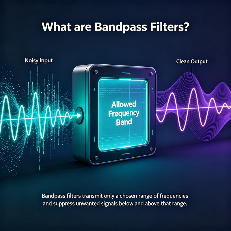
A bandpass filter (BPF) is a frequency-selective circuit or algorithm that allows signals within a specific range to pass through while attenuating frequencies both above and below that range. Bandpass filters are essential in radio receivers, wireless transmitters, audio equalizers, optical instruments, and any system that must isolate a desired signal from a crowded spectrum.

What are Bandpass Filters

Quick Answer

A bandpass filter passes a band of frequencies between a lower cutoff frequency (fL) and an upper cutoff frequency (fH), and rejects everything outside that band. It is essentially a combination of a lowpass filter and a highpass filter, defining a band of interest using the parameters center frequency, bandwidth, and quality factor (Q).

Bandpass Filter Definition

In formal terms, a bandpass filter is a two-port network whose magnitude response |H(f)| peaks within a passband [fL, fH] and falls off on either side. The three parameters that completely describe a bandpass response are:

  • Center Frequency (f0): the geometric or arithmetic midpoint of the passband.
  • Bandwidth (BW): fH − fL, the width of the passband.
  • Quality Factor (Q): f0 / BW, describing how narrow the filter is relative to its center.

A high-Q bandpass filter has a very narrow passband and sharp selectivity; a low-Q filter passes a wider band with gentler skirts.

How a Bandpass Filter Works

A bandpass filter can be built in three principal ways:

  1. Wideband approach: cascade a highpass filter and a lowpass filter. The passband is the overlap of their individual passbands.
  2. Resonant approach: use an LC, ceramic, SAW, crystal, or cavity resonator that naturally peaks at f0 and rolls off on either side.
  3. Digital approach: implement the filter mathematically using FIR or IIR coefficients in software.

Typical Bandpass Frequency Response

0 dB −20 −40 −60 f fL fH f0 Passband Stopband

The shaded region is the passband; fL and fH are the −3 dB cutoff frequencies that define bandwidth (BW = fH − fL). f0 is the center frequency where the filter has minimum insertion loss.

Key Parameters Explained

Parameter Symbol Description
Center Frequency f0 Midpoint of the passband, where attenuation is lowest
Lower Cutoff fL −3 dB point on the lower side of the response
Upper Cutoff fH −3 dB point on the upper side of the response
Bandwidth BW fH − fL
Quality Factor Q f0 / BW; higher Q means narrower filter
Insertion Loss IL Signal loss within the passband (ideally 0 dB)
Stopband Rejection How much out-of-band energy is attenuated
Shape Factor SF Ratio of −60 dB to −3 dB bandwidths; 1 = ideal

Types of Bandpass Filters

Passive

LC Bandpass Filter

A series LC followed by a parallel LC (or vice versa). Standard for RF tuned circuits, IF stages, and audio crossovers.

Active

Op-Amp Bandpass Filter

Combines an op-amp with RC networks in Sallen-Key, multiple-feedback, or state-variable topologies for gain and isolation.

Mechanical

Crystal / SAW Filter

Quartz crystals and surface-acoustic-wave devices provide extremely high Q and steep skirts for RF and IF selectivity.

Cavity

Cavity & Waveguide Filter

Used at microwave frequencies for radar and satellite communications where insertion loss must be minimal.

Microstrip

Microstrip / Stripline

Printed transmission-line filters integrated on PCBs. Common in Wi-Fi, Bluetooth, and 5G modules.

Ceramic

Ceramic BPF

Compact, low-cost ceramic resonators widely used in cellular and IoT front-ends.

Digital

Digital FIR / IIR BPF

Software-implemented filters with arbitrary response, used in SDR, audio processing, and biomedical signals.

Optical

Optical Bandpass Filter

Dielectric or dye-based filters that pass a defined wavelength range; used in fluorescence microscopy and spectroscopy.

Common Bandpass Filter Responses

Topology Passband Roll-off Best For
Butterworth Maximally flat −20 dB/dec per order General-purpose, no ripple
Chebyshev Equal ripple Steeper than Butterworth Sharper cutoff, ripple tolerated
Bessel Flat, linear phase Gentle Pulse and waveform preservation
Elliptic Ripple both bands Steepest Highest selectivity per order
Gaussian Smooth bell shape Gradual Minimum group-delay distortion

Designing a Bandpass Filter

  1. Specify f0 and BW from the desired channel or frequency range.
  2. Decide on Q = f0/BW. High Q for narrow channels, low Q for wideband audio.
  3. Choose a topology based on frequency, Q, and required stability (active, passive, mechanical, digital).
  4. Select components with appropriate tolerances — LC values, op-amp GBW, or digital coefficients.
  5. Simulate with SPICE, MATLAB, or Python to verify magnitude, phase, and group delay.
  6. Build and measure with a network analyzer or spectrum analyzer, then tune component values.

Real-World Applications

Radio & Wireless Communications

  • RF front-end preselectors reject out-of-band blockers before the LNA.
  • Intermediate-frequency (IF) filters select the desired channel in super-heterodyne receivers.
  • Antenna duplexers are paired BPFs for simultaneous transmit and receive on different bands.

Audio & Music

  • Parametric equalizers use BPFs to boost or cut a specific frequency range.
  • Voice-presence filters isolate vocal frequencies around 1–4 kHz.
  • Guitar effects pedals (wah, talk-box) use resonant BPFs for tonal shaping.

Image & Signal Processing

  • Gabor bandpass filters decompose images into spatial-frequency bands.
  • Wavelet transforms use bandpass decompositions for multi-resolution analysis.
  • Seismic data processing isolates frequency bands corresponding to specific geological layers.

Biomedical & Scientific Instruments

  • EEG and ECG instrumentation filters isolate biosignal bands while rejecting line noise.
  • Spectrophotometers use optical bandpass filters to select measurement wavelengths.
  • Lock-in amplifiers use narrow BPFs to extract signals buried in noise.

Industrial & Test

  • Vibration analysis isolates specific mechanical resonances.
  • Power-line carrier communication uses BPFs to extract data from noisy mains wiring.
  • Spectrum analyzers use BPFs as resolution filters for swept measurements.
Design Trade-off: Higher Q gives sharper selectivity but increases insertion loss, group delay, and sensitivity to component tolerances. Always balance selectivity against the bandwidth and stability of the signal you want to capture.

Common Mistakes

  • Impedance mismatch: a BPF designed for 50 Ω loses its shape if loaded with a different impedance.
  • Excessive Q: causes ringing on transient signals and makes tuning difficult.
  • Ignoring temperature drift: LC and crystal filters shift with temperature; choose components with stable coefficients.
  • Mixing topology choices: cascading a Butterworth with a Chebyshev can produce unexpected passband ripple.
  • Forgetting group delay: in digital communications, unequal delay across the band causes intersymbol interference.

Key Takeaways

  • A bandpass filter passes frequencies between fL and fH while attenuating everything else.
  • Center frequency, bandwidth, and Q factor fully describe its response.
  • It can be built from cascaded HPF + LPF, LC resonators, mechanical resonators, or digital algorithms.
  • BPFs are essential in RF, audio, biomedical, optical, and industrial systems.
  • Higher Q means sharper selectivity but greater sensitivity to component tolerances and group delay.

Frequently Asked Questions

What is a bandpass filter?

A bandpass filter is a circuit or algorithm that allows signals within a specific frequency range to pass while attenuating frequencies above and below that range. It is defined by its center frequency, bandwidth, and Q factor.

What is the difference between bandpass and lowpass filters?

A lowpass filter passes all frequencies below its cutoff. A bandpass filter passes only a band between two cutoffs, blocking both lower and higher frequencies.

How do you calculate Q factor?

Q = f0 / BW, where f0 is the center frequency and BW is the −3 dB bandwidth. A higher Q indicates a narrower filter.

Where are bandpass filters used?

They are used in radio receivers, Wi-Fi and cellular front-ends, audio equalizers, optical instruments, biomedical signal processing, vibration analysis, and many other applications that need to isolate a desired frequency band.

Can a bandpass filter be made with software?

Yes. Digital bandpass filters are implemented with FIR or IIR coefficients in software. They are highly flexible and free of component tolerances, making them the preferred choice in software-defined radio and digital audio processing.

About the Author — MeiXun Team

Wang

Chief Engineer Wang

High-tech Enterprise, Feifeng Talent

Chief Engineer Wang graduated with a master's degree in high-power microwave from the Institute of Electronics, University of Chinese Academy of Sciences.

View Full Profile
Wang

Chief Engineer Wang

High-tech Enterprise, Feifeng Talent

Chief Engineer Wang graduated with a master's degree in high-power microwave from the Institute of Electronics, University of Chinese Academy of Sciences.

In the same year, he joined CETC 40/41 for work and study. He has been committed to the design and development of microwave switches for a long time.

He has applied for 27 patents as the first inventor in the microwave switch field, with 6 authorized invention patents and 14 utility model patents.

The products he developed cover various application platforms such as civilian testing, vehicle-mounted, shipborne, airborne, and missile-borne.

RF Microwave Switch RF Switch Coaxial Switch PIN Diode Switch Low Noise Amplifier Waveguide Switch PIN Switch Microwave Switch