Band Stop Filters 101: Definition, Use Cases and Design Tips
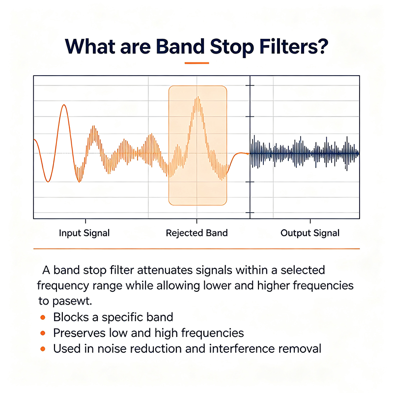
A band stop filter (BSF) — also called a band reject or notch filter — is a frequency-selective network that attenuates signals within a specific band while passing all frequencies above and below it. Band stop filters are indispensable for removing interference, rejecting narrow-band noise, and protecting sensitive electronics from unwanted spectral content.
Quick Answer
A band stop filter passes frequencies outside a defined stopband and attenuates those inside it. When the stopband is narrow it is called a notch filter; when it is wide it is called a band reject filter. The response is essentially the inverse of a bandpass filter, and it is widely used to remove 50/60 Hz hum, reject TV-band interference, suppress RF carriers, and clean up power-line communication noise.
Band Stop Filter Definition
Formally, a band stop filter is a two-port network whose magnitude response |H(f)| is near unity for frequencies below the lower cutoff fL and above the upper cutoff fH, while attenuating frequencies between them. Three parameters describe the response:
Center Frequency (f0): the midpoint of the rejected band.
Stopband Bandwidth (BW): fH − fL.
Notch Depth: the maximum attenuation within the stopband, typically 20 to 60 dB or more.
A common special case is the notch filter, where BW is very narrow and the filter removes a single interfering tone (e.g., 50 Hz mains hum or a CW radar signal).
How a Band Stop Filter Works
Typical Band Stop Frequency Response
Frequencies between fL and fH fall into the stopband and are attenuated, while everything outside that band passes through. The deepest notch occurs at the center frequency f0.
Band stop filters are usually built using one of three architectural approaches:
Passive LC ladder: a parallel LC trap in series with the line creates a high impedance at f0, blocking the unwanted band.
Active twin-T or Wien-bridge notch: combines RC lowpass and highpass paths to produce deep rejection at a single frequency.
Digital IIR/FIR notch: implements the response mathematically, ideal for removing single-frequency interference from data.
Notch Filter vs. Band Reject Filter
Aspect
Notch Filter
Band Reject Filter
Stopband Width
Very narrow (< 5% of f0)
Wide (10% – 90% of f0)
Typical Use
Single-tone interference removal
Reject a whole sub-band
Implementation
Twin-T, lattice, FIR comb
LC ladder, cavity, ceramic
Example
60 Hz hum removal
Reject 88 – 108 MHz FM band
Types of Band Stop Filters
Passive
LC Notch Filter
A parallel LC tank placed in series with the signal path creates a notch at f0 = 1/(2π√LC). Simple and rugged.
Active
Twin-T Notch Filter
Classic op-amp topology providing deep nulls (>40 dB) at a single frequency with good Q control.
Active
Wien-Bridge Notch
Selective notch with independent Q adjustment; popular in audio feedback suppression.
Mechanical
Cavity / Waveguide Notch
Microwave cavities tuned to reject a specific carrier or radar signal with very high Q.
Microstrip
Microstrip Stub Notch
An open or shorted transmission-line stub presents an open circuit at its quarter-wave frequency.
Crystal
Crystal / SAW Notch
Piezoelectric resonators with extremely high Q for very narrow, deep rejection.
Ceramic
Ceramic Trap Filter
Compact ceramic resonators for cellular and IoT band rejection (e.g., LTE band 13).
Digital
Digital IIR / FIR Notch
Software-implemented notch with adaptive frequency tracking; ideal for biomedical and audio DSP.
Key Specifications
Parameter
Description
Center Frequency (f0)
Midpoint of the rejection band
Notch Depth
Maximum attenuation within the stopband (40–60 dB typical)
−3 dB Bandwidth
Width of the stopband at the −3 dB attenuation points
Quality Factor (Q)
f0 / BW; controls selectivity and ringing
Passband Ripple
Allowed variation outside the stopband
Stopband Rejection
Minimum attenuation over the entire stopband
Insertion Loss
Loss in the passband (ideally 0 dB)
Group Delay
Time delay; high Q introduces ringing near f0
Real-World Use Cases
1. Mains Hum Removal (50/60 Hz)
The most common audio application: a narrow notch at 50 Hz or 60 Hz removes mains interference from biomedical, instrumentation, and live-audio signals without affecting surrounding audio content.
2. RF Interference Rejection
Reject AM broadcast (535 – 1700 kHz) when listening to shortwave.
Suppress commercial FM (88 – 108 MHz) in professional wireless microphone receivers.
Block cellular bands from sensitive scientific receivers.
3. Power-Line Communication (PLC) & EMI
PLC systems inject data onto mains wiring. A band stop filter isolates the data band (often 30 – 500 kHz) so it doesn't disturb audio systems or other equipment sharing the same line.
4. Audio Feedback Suppression
Live-sound consoles deploy automatic notch filters that detect and cancel feedback frequencies in real time, often reducing 5 – 10 dB of ringing without affecting program material.
5. TV Band & Radar Rejection
After the digital TV transition, many countries freed the 700 MHz band for wireless microphones. Notch filters suppress legacy TV carriers and strong radar pulses in shared spectrum.
6. Optical & Imaging
Notch filters block laser-line wavelengths in fluorescence microscopy.
Optical band-stop filters remove unwanted ambient colors in machine-vision systems.
Pro Tip: For adaptive interference, pair a band stop filter with a frequency-tracking PLL or an LMS adaptive algorithm. This converts a fixed notch into a self-tuning solution that follows drifting interference such as motor whine or variable-speed drives.
Design Tips
1. Choose Q Carefully
High Q gives deep, narrow notches but causes ringing on transients. Use the lowest Q that achieves your required stopband depth.
2. Match Impedance
LC and microstrip notch filters are designed for a specific source and load impedance (often 50 Ω or 75 Ω). Mismatches shift f0 and reduce notch depth.
3. Account for Temperature Drift
LC components drift with temperature. For stable notches, use NP0/C0G capacitors or digital implementations that retune themselves.
4. Cascade for Steeper Roll-off
Two cascaded notch filters can produce >60 dB rejection and a wider flat-bottom stopband without raising Q too high.
5. Add a Pre-filter
Combine a band stop filter with a bandpass or lowpass filter when you need both rejection and bandwidth limitation. The pre-filter protects the notch from overload.
6. Simulate Before Building
Tools like LTspice, QUCS, RFsim99, or Python SciPy predict insertion loss, group delay, and tuning sensitivity in minutes. Always simulate before committing to hardware.
7. Measure Real Notch Depth
Network analyzer or swept sine measurements are essential. A notch that "looks" deep in simulation can be shallower due to parasitics.
8. Consider Adaptive Filters
When the interference frequency drifts, use an adaptive notch filter driven by an LMS or RLS algorithm that tracks the unwanted tone automatically.
Common Mistakes
Tuning to the wrong frequency: tolerance stack-up can shift f0 by 10 % or more; always measure and trim.
Excessive Q: deep notches require high Q, but high-Q filters ring badly on impulses — balance is everything.
Forgetting source/load impedance: an LC notch assumes 50 Ω; PCB parasitic capacitance can detune it.
Over-cascading: each stage adds insertion loss; more than 3 stages of narrow notch filters usually degrade SNR.
Ignoring group delay variation: digital communications can suffer ISI if notches coincide with the data bandwidth.
Band Stop vs. Band Pass Filter
Aspect
Band Stop
Band Pass
Response Shape
Inverse "U" — passes outside, blocks inside
"U" — passes inside, blocks outside
Common Use
Reject interference
Select desired signal
Twin-T equivalent
Yes (notch configuration)
Yes (bandpass configuration)
Combined
Cascading a band stop with a band pass yields highly selective filtering for crowded spectrum
Key Takeaways
A band stop filter passes frequencies outside its stopband and rejects those inside it.
Notch filters are narrow-band band stop filters, ideal for single-tone interference removal.
Implementation choices include LC traps, twin-T active circuits, mechanical resonators, microstrip stubs, and digital IIR/FIR filters.
Common applications: 50/60 Hz hum removal, RF interference rejection, audio feedback control, and optical line blocking.
Design tips: balance Q with group delay, match impedance, simulate, and consider adaptive tracking for drifting interference.
Frequently Asked Questions
What is a band stop filter?
A band stop filter is a circuit or algorithm that attenuates a specific band of frequencies while passing all others. It is the inverse of a bandpass filter and is widely used to remove interference.
What is a notch filter?
A notch filter is a band stop filter with a very narrow stopband. It removes a single interfering tone, such as 50 Hz or 60 Hz mains hum, without disturbing nearby frequencies.
What is the difference between band stop and band reject filters?
They are functionally the same — both attenuate a band of frequencies. "Band reject" is often used for wider stopbands, while "notch" refers to very narrow ones.
How deep can a notch filter go?
Active twin-T notch filters can reach 40 – 50 dB of attenuation. Cascading two stages or using mechanical resonators (cavity, crystal) can exceed 60 – 80 dB.
Can a band stop filter be made adaptive?
Yes. Digital IIR notch filters with LMS or RLS adaptation can automatically track drifting interference frequencies, making them useful for motor whine, variable-speed drives, and biomedical applications.
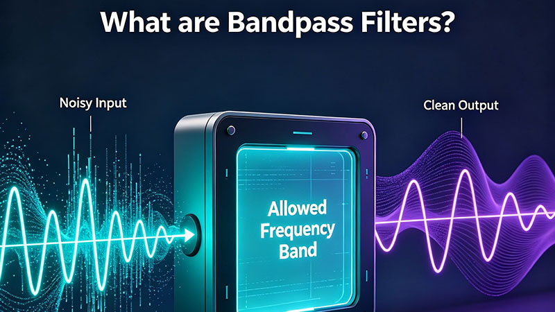
What are bandpass filters? Learn how a band pass filter works, its key parameters (center frequency, bandwidth, Q factor), the main types and topologies, and where BPFs are used in RF, audio, optics, and communications.
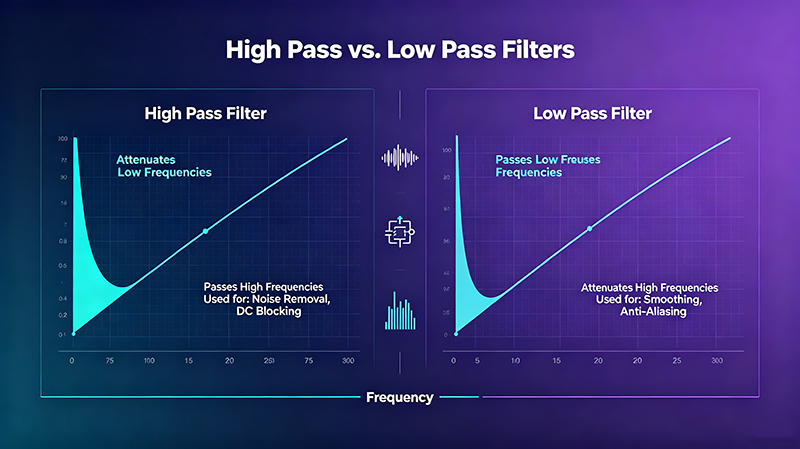
High pass vs. low pass filters — discover the key differences, how each works, where they are used, and how to choose the right filter for your audio, RF, image processing, or power-electronics application.
Aug 28 ,26
About the Author — MeiXun Team
Wang
Chief Engineer Wang
High-tech Enterprise, Feifeng Talent
Chief Engineer Wang graduated with a master's degree in high-power microwave from the Institute of Electronics, University of Chinese Academy of Sciences.
View Full Profile
Wang
Chief Engineer Wang
High-tech Enterprise, Feifeng Talent
Chief Engineer Wang graduated with a master's degree in high-power microwave from the Institute of Electronics, University of Chinese Academy of Sciences.
In the same year, he joined CETC 40/41 for work and study. He has been committed to the design and development of microwave switches for a long time.
He has applied for 27 patents as the first inventor in the microwave switch field, with 6 authorized invention patents and 14 utility model patents.
The products he developed cover various application platforms such as civilian testing, vehicle-mounted, shipborne, airborne, and missile-borne.