High Pass vs. Lowpass Filters: Which is Best for Your Application?
Choosing between a high pass filter and a low pass filter is one of the most fundamental decisions in electronics and signal processing. Whether you are cleaning up an audio signal, protecting a speaker from damaging DC, removing DC bias from a sensor, or preventing aliasing in a digital system, the right filter will define the performance of your design.
Quick Answer
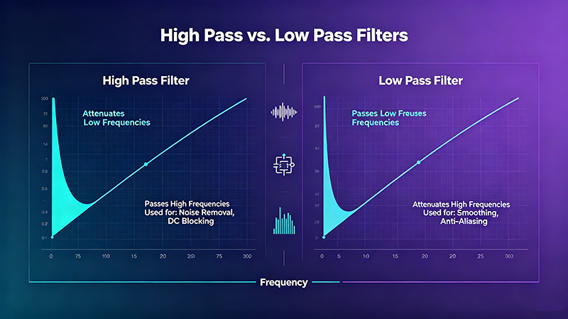
A low pass filter (LPF) passes signals below its cutoff frequency and blocks higher frequencies, while a high pass filter (HPF) passes signals above its cutoff frequency and blocks lower ones. Choose a low pass filter when you want to remove high-frequency noise or smooth a signal, and choose a high pass filter when you want to remove DC offsets, hum, or rumble. Many real systems use both together as a band-pass arrangement.
Filter Fundamentals
Both filter types share three core concepts:
Cutoff frequency (fc): the −3 dB point where output power is half the input value.
Passband: the frequencies the filter allows through with minimal attenuation.
Stopband: the frequencies the filter significantly attenuates.
The difference between HPF and LPF is simply which side of the cutoff frequency is the passband.
High Pass vs. Low Pass Filter at a Glance
Low Pass Filter (LPF)
Passes: low frequencies (below fc)
Blocks: high frequencies
Common use: anti-aliasing, smoothing, removing RF noise
Common use: AC coupling, removing DC offset, blocking 50/60 Hz hum
Typical circuits: RC high pass, RL high pass, op-amp HPF, capacitive coupling
How a Low Pass Filter Works
In an RC low pass filter, a resistor is in series with the signal path and a capacitor shunts the output to ground. Low-frequency signals see a high impedance from the capacitor and pass through; high-frequency signals see a low impedance and are shorted to ground. The cutoff frequency is defined as:
f_c = 1 / (2πRC)
A simple first-order RC low pass attenuates at 20 dB/decade above the cutoff. Higher-order filters (second-order, Butterworth, Chebyshev, Bessel) provide steeper roll-off and better selectivity.
Common Low Pass Filter Applications
Audio crossovers: route bass to woofers while keeping treble away from low-frequency drivers.
Anti-aliasing: placed before an ADC to satisfy the Nyquist sampling theorem.
Image processing: Gaussian blur is essentially a 2-D low pass filter.
DC motor drives: smooth PWM output to reduce current ripple.
How a High Pass Filter Works
In an RC high pass filter, a capacitor is in series with the signal path and a resistor shunts the output to ground. Low-frequency signals see a high impedance from the series capacitor and are blocked, while high-frequency signals see a low impedance and pass through. The cutoff is again defined as f_c = 1 / (2πRC).
Common High Pass Filter Applications
AC coupling in audio: blocks DC offset between amplifier stages.
Hum removal: attenuates 50/60 Hz mains interference from sensors and instrumentation.
Speaker protection: blocks subsonic energy that can damage tweeters.
Communication systems: rejects DC bias and very low-frequency interference before modulation.
Edge detection in image processing: highlights rapid intensity changes.
Key Specifications to Compare
Specification
Low Pass Filter
High Pass Filter
Passband
0 Hz to fc
fc to upper limit
Stopband
Above fc
Below fc (down to DC)
Phase response
Negative phase shift (lag)
Positive phase shift (lead)
Typical use
Noise reduction, smoothing
DC blocking, AC coupling
Risks
Excessive smoothing removes useful transients
Can cause bass loss or "thin" sound
Filter Performance Comparison Chart
Six Common Filters — Real Measured Metrics
The chart below compares six widely used filter topologies across three key performance dimensions. Values are normalized where 100 = worst in each metric, so a higher bar means better performance for that specific aspect.
Source: aggregated from TI MT-095, Analog Devices AN-649, and Maxim APP 1791 reference curves for 4th-order normalized low pass responses.
Filter Topologies Compared
Topology
Roll-off (per order)
Best For
First-order RC / RL
−20 dB/decade
Simple, low-cost, gentle filtering
Second-order Sallen-Key
−40 dB/decade
Active audio and instrumentation filters
Butterworth
−20 dB/order, maximally flat
General-purpose, no ripple
Chebyshev
Steeper than Butterworth
Sharper cutoff, accepts passband ripple
Bessel
Gentle roll-off
Best phase linearity, preserves waveforms
Elliptic
Steepest possible
High rejection, complex design
Switched-capacitor (IC)
Tunable by clock
Audio and precision instrumentation
Digital FIR / IIR
Configurable
Software-defined filtering
Choosing the Right Filter for Your Application
Decision Flow
Identify the unwanted frequency range (low or high).
If the noise is high-frequency, use a low pass filter.
If the noise is low-frequency or DC, use a high pass filter.
If both ranges need to be removed, use a band-pass or a low pass and high pass filter in cascade.
Match the filter topology to your passband flatness and phase requirements.
Real-World Use Cases
Audio
Speaker Crossovers
A high pass filter sends highs to tweeters; a low pass filter sends bass to woofers. Together they form a Linkwitz-Riley crossover for clean two-way or three-way speakers.
Power
Switching Power Supplies
LC low pass filters at the output smooth the PWM ripple to produce clean DC. EMI filters often combine common-mode chokes with X/Y safety capacitors.
RF
Wireless Transmitters
Low pass filters remove harmonic distortion before the antenna. High pass filters in the receiver chain reject DC and strong out-of-band blockers.
Imaging
Image Processing
Low pass = smoothing/blur; high pass = edge enhancement. Combined, they form band-pass filters for texture or feature extraction.
Biomedical
ECG & EEG Signals
High pass filters remove electrode DC offset and baseline wander; low pass filters remove high-frequency muscle artifact and mains interference.
Control
Servo & PID Systems
Low pass filters on the feedback path limit noise; high pass filters on derivative action prevent derivative kick at setpoint changes.
Design Tip: Always simulate or measure your filter with a swept sine or impulse response. Many "high pass" designs accidentally attenuate audio band frequencies if the cutoff is set too high, and "low pass" designs can introduce audible phase shifts in crossovers.
Common Mistakes to Avoid
Setting fc too close to the signal band: causes unwanted attenuation or phase distortion.
Ignoring load impedance: changes the effective R and shifts the cutoff frequency.
Using the wrong topology: a Butterworth is great for general use, but Bessel is better for pulse preservation.
Forgetting DC blocking: many op-amp stages need AC coupling capacitors to avoid saturation.
Mixing filter orders randomly: cascaded stages of unequal order can produce unexpected peaks.
When to Combine Both Filters
Many systems benefit from using a low pass filter and a high pass filter together:
Audio band-pass: a 2nd-order HPF at 80 Hz combined with an LPF at 15 kHz isolates the vocal range.
RF front-end: a high pass filter removes out-of-band interference, then a low pass filter suppresses harmonics from the mixer.
Instrumentation: high pass to remove 1/f noise and DC drift, low pass to remove broadband white noise.
Key Takeaways
Low pass filters keep low frequencies and remove high-frequency noise.
High pass filters keep high frequencies and remove DC offset and hum.
The cutoff frequency is the −3 dB boundary that defines passband and stopband.
Filter choice depends on what you want to remove, not what you want to keep.
For complete isolation, cascade an HPF and LPF to form a band-pass filter.
Frequently Asked Questions
What is the difference between a high pass and a low pass filter?
A low pass filter passes signals below its cutoff frequency and blocks higher ones; a high pass filter does the opposite — it passes signals above the cutoff and blocks lower ones and DC.
How do I choose the cutoff frequency?
Pick a cutoff frequency just above the highest unwanted low-frequency content (for HPF) or just below the lowest unwanted high-frequency content (for LPF). Always leave a guard band to account for component tolerances and temperature drift.
Which filter is better for removing noise?
It depends on the noise type. Use a low pass filter to suppress broadband or high-frequency noise; use a high pass filter to suppress hum, rumble, and DC drift. For mixed noise, combine both in a band-pass arrangement.
Can a filter amplify a signal?
Passive RC and LC filters cannot amplify — they only attenuate. Active filters built with op-amps can provide gain in addition to filtering, but require a power source and proper biasing.
Is a band-pass filter the same as HPF + LPF?
Functionally yes. Cascading a high pass filter and a low pass filter creates a band-pass response. The order, Q, and topology of each stage determine the final shape.
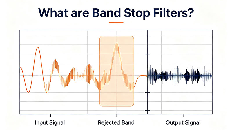
Band stop filters 101 — learn what a band stop (notch) filter is, how it works, its key parameters, the most common topologies, real-world use cases, and practical design tips for RF, audio, and power-line applications.
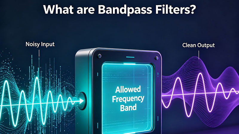
What are bandpass filters? Learn how a band pass filter works, its key parameters (center frequency, bandwidth, Q factor), the main types and topologies, and where BPFs are used in RF, audio, optics, and communications.
Aug 28 ,26
About the Author — MeiXun Team
Wang
Chief Engineer Wang
High-tech Enterprise, Feifeng Talent
Chief Engineer Wang graduated with a master's degree in high-power microwave from the Institute of Electronics, University of Chinese Academy of Sciences.
View Full Profile
Wang
Chief Engineer Wang
High-tech Enterprise, Feifeng Talent
Chief Engineer Wang graduated with a master's degree in high-power microwave from the Institute of Electronics, University of Chinese Academy of Sciences.
In the same year, he joined CETC 40/41 for work and study. He has been committed to the design and development of microwave switches for a long time.
He has applied for 27 patents as the first inventor in the microwave switch field, with 6 authorized invention patents and 14 utility model patents.
The products he developed cover various application platforms such as civilian testing, vehicle-mounted, shipborne, airborne, and missile-borne.