

























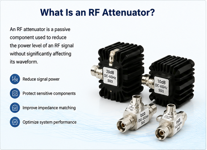
RF attenuators are essential passive components used in radio frequency and microwave systems to reduce signal power while maintaining impedance matching and signal integrity.
Jul 27 ,26


5G communication testing, wireless terminal automated testing
Aerospace communication systems
Precision measurement equipment, radio frequency signal control of radar transmitters
Communication and navigation systems
Optical communication module-related testing
Interconnection of wireless communication base stations
Every RF attenuator has three power limits: average (CW) power (limited by heat dissipation), peak power (limited by breakdown / arcing), and pulse energy (limited by average over time). To avoid burnout, never operate at the rated maximum, observe VSWR derating, verify pulse waveform, and confirm the attenuator can handle reflected power under load mismatch.
The continuous power the attenuator can absorb indefinitely without exceeding its maximum internal temperature. Limited by the resistor network's heat dissipation. A 50 Ω attenuator rated at 2 W continuously must dissipate the full input power minus the small fraction reflected by the load.
The maximum instantaneous power the attenuator can survive without arcing or breakdown. Limited by the voltage across the resistive elements and the dielectric strength of the package. Peak rating is typically 100× – 1000× higher than the CW rating.
The energy per pulse must stay low enough that the average power — pulse energy × pulse repetition frequency — remains below the CW rating. Even if peak power is below the peak rating, repeated pulses can heat the attenuator beyond its thermal limit.
Overheating burns through the thin-film resistor, leaving an open circuit. Attenuation becomes infinite.
Sustained overheating increases resistance beyond spec. SWR and attenuation degrade.
Peak over-voltage creates an arc between resistive elements. Permanent short or open results.
Repeated thermal cycling cracks solder joints, especially in high-power units.
Repeated over-power cycles degrade connector plating, raising contact resistance.
Load mismatch reflects power back into the attenuator, doubling absorbed power at worst case.
Use the attenuator at 50 – 80 % of its rated CW power. This margin accounts for:
Peak power should also be derated, especially in pulse systems. A 1 kW peak / 1 % duty cycle signal has the same average power as a 10 W CW signal. But peak voltage is still 1000 W peak — which can arc.
With VSWR = 1.5:1, reflected power adds to dissipated power. At VSWR = 2:1, up to 11 % of incident power returns, increasing heating. At VSWR = 3:1 or higher, the combined heating can exceed the CW rating. Always add margin for the worst-case load.
Average power for a pulsed signal is:
Pavg = Ppeak × duty cycle
For example: 1 kW peak at 0.1 % duty cycle = 1 W average. The attenuator only needs to dissipate 1 W, but the peak voltage is still 1 kW / 50 Ω = 316 V peak. If the attenuator is rated for 100 V peak, it will arc.
Always check average and peak independently against.
| Specification | Meaning |
|---|---|
| Average Power | Maximum continuous dissipation (W) |
| Peak Power | Maximum instantaneous power (W or kW) |
| Pulse Width | Maximum single-pulse duration |
| Duty Cycle | Maximum pulse duty cycle for rated peak |
| Frequency Range | Operating band for power ratings |
| VSWR | Maximum tolerated mismatch |
| Operating Temperature | Case temperature limits |
| Derating Curve | Power vs. temperature |
Add a circulator or limiter upstream of the attenuator to absorb reflections and spikes.
Always confirm the load is connected and at proper VSWR before applying RF power.
Mount attenuators to a heat sink or chassis. Forced air extends power handling.
Use thermal sensors or IR cameras during integration to verify hot spots stay within limits.
Bring RF power up slowly so transient overshoot does not exceed the peak rating.
Use precision connectors and cables to minimize reflections back into the attenuator.
Attenuators near rating degrade faster. Track cumulative exposure and replace proactively.
Check resistance, VSWR, and connector wear. Replace when attenuation drifts by 0.5 dB or more.
Used in a cellular test bed to bring 100 W amplifiers down to receiver levels. Safe at 5 W CW with 50 % derating, but cannot survive a 200 W pulse spike.
Used at the output of a high-power broadcast transmitter. Requires a heat sink and forced air; a momentary load disconnect can arc the internal resistor.
Inside a radar front-end. The duty cycle keeps average power low, but peak must be derated for the pulse waveform and any load mismatch.
Average power is the continuous dissipation the attenuator can absorb indefinitely. Peak power is the maximum instantaneous spike the attenuator can survive without arcing.
Operate at 50 – 70 % of the rated CW power. Add further margin for high VSWR, elevated temperature, and pulsed waveforms.
Yes. Reflected power adds to dissipated power. At VSWR=2:1, up to 11 % of incident power returns. At VSWR=3:1 or higher, the combined heating can exceed the CW rating.
The dielectric strength of the resistive elements and connector insulation. Peak rating is typically 100× – 1000× the CW rating.
Generally no. Burnt resistive elements cannot be reliably restored. Replace the attenuator and review your power budget to prevent recurrence.
High-tech Enterprise, Feifeng Talent
Chief Engineer Wang graduated with a master's degree in high-power microwave from the Institute of Electronics, University of Chinese Academy of Sciences.
View Full Profile