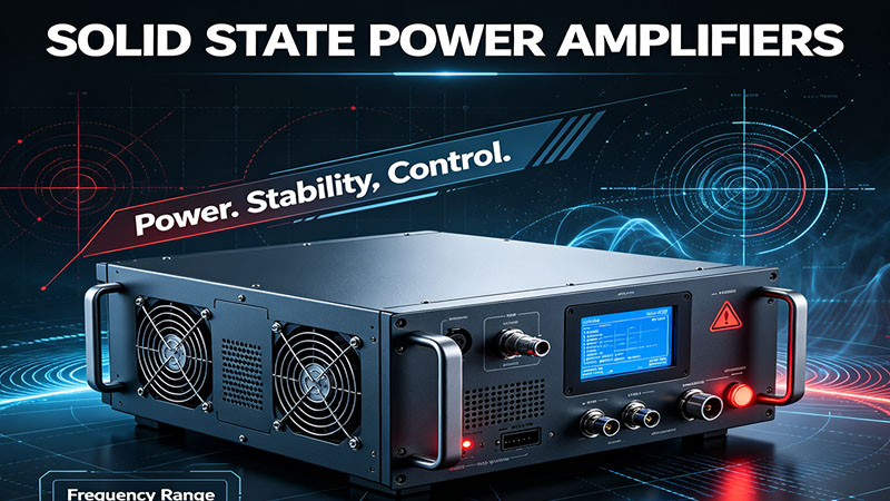
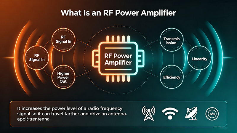
An RF power amplifier module is a fully integrated RF amplifier assembly — typically a small PCB with one or more transistor dies, matching networks, bias circuits, and thermal management. Modules deliver ready-to-use high-power RF for cellular, Wi-Fi, radar, satcom, and industrial systems without requiring designers to build the amplifier from discrete parts.
Quick Answer
An RF power amplifier module combines a power transistor (GaN, LDMOS, GaAs), input/output matching, bias sequencing, and thermal management into a single drop-in package or PCB assembly. Designers connect DC supply and RF in/out, apply a small control signal (enable, gain select), and the module delivers specified output power. Modern modules include on-board protection for over-temperature, over-current, and VSWR mismatch.
What Is an RF Power Amplifier Module?
Unlike a discrete transistor that requires external matching, bias, and protection, an RF PA module is a complete subassembly. It typically includes:
-
Power transistor die(s): GaN HEMT, LDMOS, GaAs pHEMT, or SiGe.
-
Input matching network: transforms 50 Ω to the optimal source impedance.
-
Output matching network: transforms the device load-line impedance to 50 Ω.
-
Bias sequencing circuit: applies gate/drain voltages in correct order.
-
Enable / shutdown control: logic-level pin to turn the amplifier on and off.
-
Protection circuitry: over-temperature, over-current, VSWR foldback.
-
Thermal interface: copper flange, baseplate, or heat-spreader.
The result is a "black box" amplifier with RF input, RF output, DC supply, and a few control pins — exactly what system designers want for fast integration.
Internal Architecture
RF Input
→
Input Match
→
Driver Stage
→
Power Stage
→
Output Match
→
RF Output
Most modules cascade two or three amplifier stages:
-
Driver stage: small-signal gain block (often MMIC) that brings input to the level the final stage needs.
-
Final / power stage: large transistors operating near P1dB for linearity or saturation for max power.
-
Combiner: in high-power modules, multiple transistors in parallel are combined into a single output.
Types of RF Power Amplifier Modules
GaN
GaN HEMT Module
Highest power density and broadband operation. Used in radar, EW, satcom. Handles multi-octave bands up to W-band.
LDMOS
LDMOS Module
Dominant in sub-6 GHz cellular and broadcast. Excellent efficiency with DPD. Mature supply chain and predictable performance.
GaAs
GaAs pHEMT Module
Lower power but excellent linearity and noise. Used for Wi-Fi drivers and microwave link boosters.
Packaged
Hermetic Module
Metal-ceramic package sealed against humidity. Used in military, aerospace, and high-reliability industrial applications.
Open-Frame
Open-Frame Module
PCB assembly with exposed flange for direct heatsink mounting. Lower cost than hermetic, used in commercial systems.
Miniature
Miniature / SMT Module
Small surface-mount package for low-power applications like IoT, Wi-Fi, and small cell. 50 Ω input/output, drop-in.
Doherty
Doherty Module
Optimized for high efficiency at backed-off power. Standard for cellular base stations running OFDM.
Broadband
Ultra-Broadband Module
Multi-octave coverage for EW and test equipment. Replaces banks of narrowband amplifiers with a single part.
Key Specifications
|
Specification
|
Meaning
|
Typical Range
|
|
Frequency Range
|
Operating band
|
10 MHz – 50 GHz
|
|
Output Power (Psat)
|
Maximum CW output
|
1 W – 1 kW
|
|
Small-Signal Gain
|
Linear gain across band
|
20 – 60 dB
|
|
Gain Flatness
|
Variation across band
|
±1 – ±3 dB
|
|
PAE
|
Power-added efficiency
|
30 – 70 %
|
|
ACPR / Linearity
|
Adjacent-channel power ratio
|
−30 to −55 dBc
|
|
Supply Voltage
|
DC rail
|
5 – 50 V
|
|
Quiescent Current
|
Idle current
|
0.2 – 5 A
|
|
VSWR Tolerance
|
Max mismatch without damage
|
3:1 – 10:1
|
|
Thermal Resistance
|
Junction-to-case temp rise
|
0.1 – 5 °C/W
|
|
Control Interface
|
Enable, gain select, alarm
|
CMOS / TTL / SPI
|
|
Form Factor
|
Mechanical package
|
SMT, flange, connectorized
|
Module vs. Discrete Design
|
Aspect
|
Module
|
Discrete Design
|
|
Design Time
|
Hours
|
Weeks
|
|
RF Expertise Required
|
Low
|
High
|
|
Cost per Watt
|
Moderate – high
|
Low – moderate
|
|
Form Factor
|
Defined
|
Custom
|
|
Optimization
|
Limited to module
|
Full control
|
|
Supply Chain
|
Single part number
|
Many components
|
Modules are ideal for volume production where design time matters more than per-unit cost savings. Discrete is preferred for unique requirements or extreme performance.
Integration Steps
-
Choose a module that covers your frequency, power, and linearity needs.
-
Design the DC supply with proper sequencing and decoupling.
-
Provide 50 Ω RF traces with controlled impedance.
-
Mount the module on a heat-sink sized for thermal dissipation.
-
Wire enable and gain-control signals with proper debouncing.
-
Add external circulators or isolators if load mismatch is expected.
-
Verify performance with S-parameter, power, and ACPR tests.
Thermal Management
RF PA modules convert 30 – 60 % of input DC into RF; the rest becomes heat. A 50 W module with 50 % efficiency must dissipate 50 W. Heat is removed by:
-
Conduction: copper flange bolted to a heat-sink or cold plate.
-
Forced air: fans blowing across the heat-sink fins.
-
Liquid cooling: cold plate with circulating water or refrigerant.
-
Heat pipes / vapor chambers: spread heat from small footprints.
Always respect the manufacturer's derating curve. Reducing case temperature by 10 °C approximately doubles median lifetime.
Rule of Thumb: For a CW module with 50 % efficiency, the heat-sink must dissipate at least as much power as the RF output. Plan airflow and surface area accordingly.
Protection Features to Look For
-
Over-temperature shutdown: automatically reduces or cuts output when junction exceeds safe limit.
-
VSWR foldback: reduces output power when load mismatch exceeds threshold.
-
Over-current protection: shuts down on DC rail fault.
-
RF overdrive detection: attenuates when input exceeds safe level.
-
Soft-start / sequencing: prevents inrush current and latch-up.
-
Status telemetry: reports faults via digital interface.
Real-World Applications
-
Cellular base stations: GaN Doherty modules at 3.5 GHz for 5G macro cells.
-
Wi-Fi 6 / 6E routers: small GaAs or GaN modules for 5 – 6 GHz bands.
-
Phased-array radar: thousands of GaN modules in T/R assemblies.
-
Satellite uplink terminals: high-linearity GaN modules with DPD.
-
Electronic warfare: broadband GaN modules covering multi-octave bands.
-
Industrial heating: LDMOS modules in 27 MHz and 40 MHz RF generators.
-
Medical imaging: MRI RF amplifiers and ultrasound transmitters.
Common Mistakes
-
Insufficient cooling: causes thermal runaway and premature failure.
-
Wrong supply sequencing: destroys GaN gates with no drain voltage.
-
Missing isolation on the output: reflected power damages the module.
-
Ignoring stability: poor grounding or decoupling causes oscillation.
-
Skipping DPD: linearity fails regulatory masks.
-
Wrong impedance PCB traces: ruins gain and efficiency.
Verification & Acceptance Testing
-
Verify small-signal gain and S-parameters over frequency.
-
Measure output power vs. input power (Pout vs. Pin).
-
Run linearity tests (ACPR, EVM) with modulated signals.
-
Verify efficiency (PAE) at typical operating power.
-
Test VSWR tolerance with a tunable mismatch load.
-
Thermal cycle and monitor case temperature.
-
Verify protection features respond correctly.
Key Takeaways
-
An RF PA module is a fully integrated amplifier assembly with matching, bias, and protection.
-
GaN modules offer highest power density; LDMOS dominates sub-6 GHz cellular.
-
Modules trade flexibility for fast integration and proven performance.
-
Thermal management is critical — plan cooling with the same care as electrical design.
-
Always respect the manufacturer's supply sequencing and protection ratings.
Frequently Asked Questions
What is an RF power amplifier module?
An RF PA module is a complete amplifier assembly containing one or more transistor dies, input/output matching networks, bias circuits, and protection features. It is designed to be drop-in, with simple DC and RF connections.
Module vs. discrete — which is better?
Modules are faster to integrate and require less RF expertise. Discrete designs offer full optimization and lower per-unit cost at volume. Choose modules for fast time-to-market; choose discrete for unique performance targets.
Which semiconductor technology should I use?
Use GaN for highest power, efficiency, and broadband above 1 GHz. Use LDMOS for sub-6 GHz cellular and broadcast. Use GaAs for low-power Wi-Fi drivers and microwave links.
Do I need a circulator?
Yes, for most applications. Modules are designed for 50 Ω loads; real antennas can present any impedance. An external circulator or isolator protects the module from reflected power.
How long do RF PA modules last?
Module lifetime depends on junction temperature and load conditions. At rated temperature and proper cooling, expect 50,000 – 100,000 hours MTBF. Excessive temperature dramatically reduces life.