




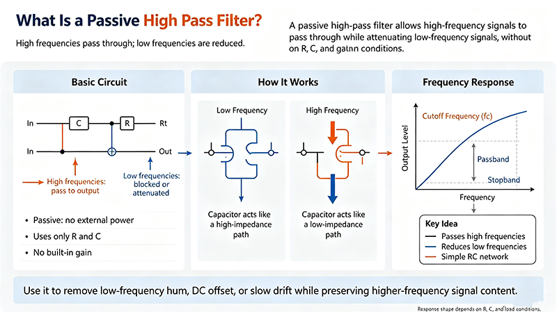
Learn what a passive high pass filter (HPF) is, how RC and RL circuits work, common topologies, cutoff frequency calculation, key specifications, applications, and design tips.
Sep 20 ,26


5G communication testing, wireless terminal automated testing
Aerospace communication systems
Precision measurement equipment, radio frequency signal control of radar transmitters
Communication and navigation systems
Optical communication module-related testing
Interconnection of wireless communication base stations
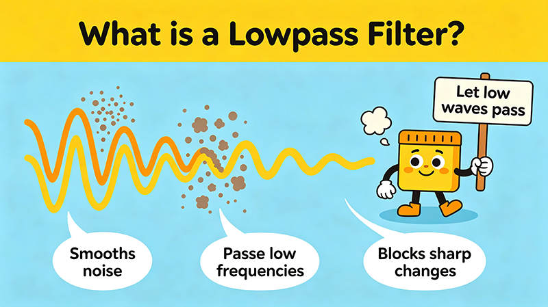
A passive low pass filter is one of the most fundamental building blocks in analog electronics. Built from only resistors, capacitors, and inductors — no amplifiers or active devices — it lets low-frequency signals pass while attenuating everything above a designed cutoff frequency. This guide explains how it works, the different topologies you can use, where it shows up in real designs, and how to choose the right one for your application.
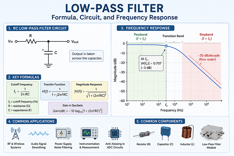
Quick answer: A passive LPF passes frequencies below its cutoff (fc) and rejects frequencies above. The simplest RC low pass filter uses one resistor and one capacitor. Cutoff is fc = 1/(2πRC). Insertion loss is at least 3 dB at fc, and rolls off at 6 dB/octave (20 dB/decade) per pole.
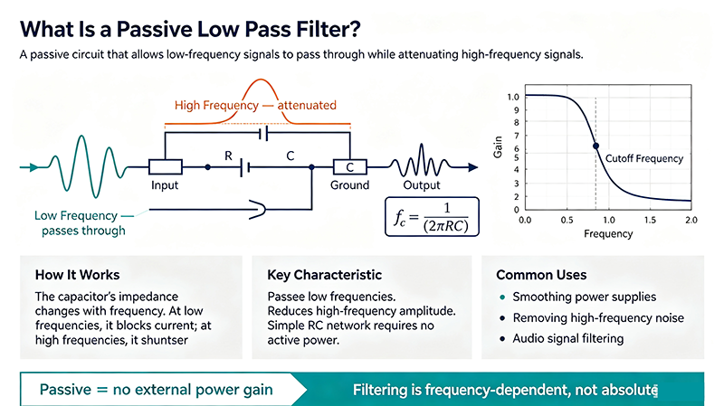
A passive low pass filter is a frequency-selective two-port network built entirely from passive components — resistors (R), capacitors (C), and inductors (L). It has no power supply, no transistors, and no op-amps. Because it cannot generate energy, it can only attenuate; it can never provide gain.
The transfer function of an ideal first-order passive low pass filter is:
At low frequencies, |H| ≈ 1 (passband). As frequency rises past the cutoff, |H| falls at 6 dB/octave per pole. Each additional RC or RL stage adds another pole, increasing roll-off steepness.
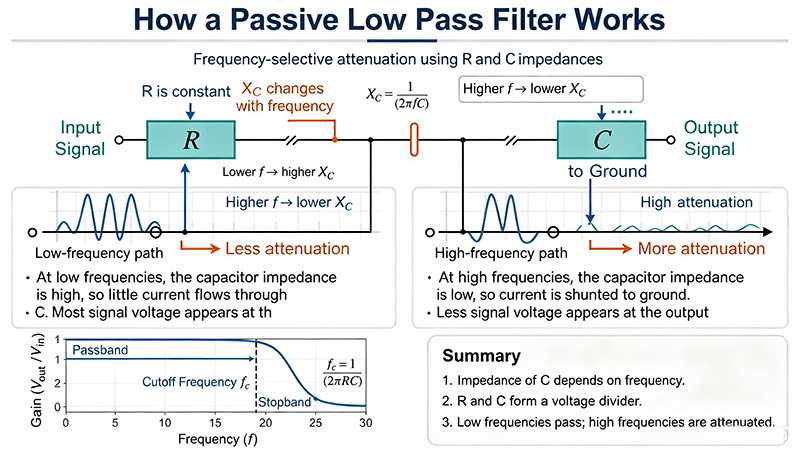
The two classic implementations exploit the natural frequency-dependence of reactive components:
A series resistor followed by a shunt capacitor to ground. At high frequencies, the capacitor's impedance (XC = 1/2πfC) drops, shunting high-frequency energy to ground.
A series inductor followed by a shunt resistor. The inductor blocks high-frequency current because XL = 2πfL rises with frequency.
Cutoff is the point where output power drops to half (-3 dB) and amplitude drops to 70.7% (-3 dB in voltage). For first-order filters:
The number of reactive elements determines the filter order, which sets the roll-off rate:
| Order | Poles | Roll-off | Stopband attenuation at 10×fc |
|---|---|---|---|
| 1st | 1 | -20 dB/decade | -20 dB |
| 2nd | 2 | -40 dB/decade | -40 dB |
| 3rd | 3 | -60 dB/decade | -60 dB |
| 4th | 4 | -80 dB/decade | -80 dB |
| 5th | 5 | -100 dB/decade | -100 dB |
Higher order gives sharper cutoff, but more stages also mean more insertion loss and component tolerance stacking.
Maximally flat passband, moderate roll-off. Best general-purpose choice when passband flatness matters.
Steeper roll-off but with passband ripple (Type I) or stopband ripple (Type II). Used where sharp cutoff is critical.
Linear phase response, minimal group delay distortion. Ideal for pulse and data signals.
Sharpest transition but ripples in both bands. Used only when steepness outweighs ripple.
Similar to Bessel; optimized for step response with no overshoot.
Monotonic passband and stopband with steepest possible transition for a given order.
| Spec | Why It Matters | Typical Range |
|---|---|---|
| Cutoff frequency fc | Defines passband/stopband boundary | 1 Hz to 10 GHz |
| Insertion loss | Signal lost in passband (passive > 0 dB) | 0.5 to 6 dB |
| Return loss / VSWR | Input/output match; affects system gain | 10 to 20 dB |
| Stopband rejection | How much unwanted signal is removed | 20 to 80+ dB |
| Group delay | Phase distortion, important for pulses | ns to μs |
| Power handling | Max CW or peak RF before damage | mW to kW |
| Impedance | Match to source/load (typically 50 Ω) | 50 / 75 Ω |
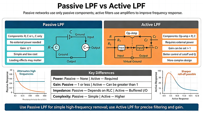
| Aspect | Passive LPF | Active LPF |
|---|---|---|
| Components | R, L, C only | Op-amp + R, C |
| Power supply | Not required | Required |
| Insertion loss | Always > 0 dB | Can be 0 dB (unity gain) |
| Max frequency | Limited by parasitic L/C | Limited by op-amp GBW |
| High-power RF | Excellent (no active devices) | Poor |
| Noise | Thermal only | Thermal + op-amp noise |
| Cost | Low | Moderate |
An RC low pass filter: one resistor in series with the signal, and one capacitor from the output to ground. Cutoff is fc = 1/(2πRC).
Passive filters need no power supply, can handle high RF power, add no noise, and are extremely cheap. For high-frequency or high-power designs, they are often the only choice.
No. Passive components cannot add energy, so the passband gain is always ≤ 0 dB. If you need gain, you must use an active topology.
With discrete LC components, cutoff can extend well into the GHz range. Above ~1 GHz, distributed-element (microstrip, stripline) filters are used instead.
Choose Butterworth for general-purpose flat response, Chebyshev for steep roll-off, and Bessel when linear phase / pulse fidelity is critical.
When operating well above cutoff, an RC low pass filter behaves like an integrator. The output approximates the time integral of the input. The transition happens around fc/2.
• A passive low pass filter uses only R, L, and C to pass low frequencies and reject high frequencies.
• Cutoff frequency is fc = 1/(2πRC) for first-order RC filters.
• Each additional pole adds 6 dB/octave of roll-off, but more insertion loss and component sensitivity.
• Choose topology by application: Butterworth (flat), Chebyshev (steep), Bessel (linear phase).
• Passive LPFs dominate in high-power RF, audio crossovers, and power-supply filtering where simplicity and reliability matter.
High-tech Enterprise, Feifeng Talent
Chief Engineer Wang graduated with a master's degree in high-power microwave from the Institute of Electronics, University of Chinese Academy of Sciences.
View Full Profile