

























Discover why high DC-RF isolation is critical in microwave bias tee design. Learn about performance impacts, design considerations, and best practices for RF engineers.
Sep 04 ,26


5G communication testing, wireless terminal automated testing
Aerospace communication systems
Precision measurement equipment, radio frequency signal control of radar transmitters
Communication and navigation systems
Optical communication module-related testing
Interconnection of wireless communication base stations

A bias tee is a three-port RF and microwave device that allows DC power and an RF signal to share the same transmission path while preventing the DC and RF components from interfering with each other. It is widely used in RF testing, microwave circuits, wireless communication, semiconductor characterization, antenna systems, and high-frequency electronics.
The basic purpose of a bias tee is simple: inject DC voltage or current into an RF signal path without significantly disturbing the RF signal. At the same time, it can separate DC and RF components at another point in the circuit.
In simple terms: a bias tee combines DC and RF onto one transmission line, while its internal components provide different impedance paths for low-frequency DC and high-frequency RF signals.
A typical bias tee consists of three ports: an RF port, a DC port, and an RF+DC port. The RF port primarily carries the high-frequency signal, the DC port supplies or receives DC power, and the combined port carries both the RF signal and DC bias.
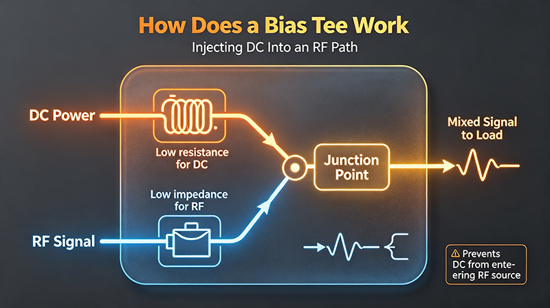
The operation of a bias tee is based primarily on the frequency-dependent behavior of two passive components: an inductor and a capacitor.
The inductor provides a low-resistance path for DC while presenting relatively high impedance to RF signals. The capacitor does the opposite: it blocks DC while allowing RF energy to pass with relatively low impedance.
As frequency increases, the impedance of an ideal inductor increases. This makes the inductor useful for preventing RF energy from entering the DC supply path.
As frequency increases, capacitive reactance decreases. Therefore, a suitable capacitor can provide a low-impedance path for RF signals while blocking DC.
In a conventional bias tee, the DC path contains an RF choke or inductor, while the RF path contains a series capacitor. These paths meet at the combined RF+DC port.
The RF port is connected to the high-frequency signal source or measurement equipment. It normally blocks DC from reaching the RF source through the series coupling capacitor.
The DC port connects to an external power supply or bias source. An RF choke helps prevent high-frequency energy from entering the DC supply.
The combined port carries both the RF signal and DC bias. It is typically connected to the device under test, amplifier, antenna, photodetector, or other active RF component.
Understanding the function of each port is essential because connecting a bias tee incorrectly can cause poor RF performance, excessive insertion loss, unexpected DC loading, or even damage to sensitive RF equipment.
The primary function of a bias tee is to introduce DC voltage or current into an RF circuit. This is especially important when an active device requires DC bias but its RF signal and power supply share the same physical transmission line.
A bias tee combines the RF and DC components at its output port. This enables a single coaxial cable or transmission path to carry both power and high-frequency information.
The series capacitor provides DC isolation between the RF port and the RF+DC port. This protects RF sources, analyzers, signal generators, and other equipment from unwanted DC voltage.
The RF choke or inductor presents high impedance to RF energy. This reduces the amount of RF power that can travel toward the DC power supply.
In laboratory environments, a bias tee can significantly simplify device characterization. Instead of using separate transmission lines for RF and DC, engineers can provide both through a single coaxial connection.
Properly designed bias tees can isolate DC from sensitive RF instruments. This is particularly useful when testing active devices that require relatively high DC bias while being connected to expensive measurement equipment.
Choosing a bias tee requires more than simply checking its operating frequency. Several electrical and mechanical specifications determine whether a particular device is suitable for an RF application.
| Specification | Why It Matters |
|---|---|
| Frequency Range | Defines the RF frequencies over which the bias tee provides acceptable performance. |
| Insertion Loss | Indicates how much RF signal power is lost through the device. |
| VSWR | Shows the degree of impedance mismatch and its effect on signal reflections. |
| Isolation | Describes how effectively RF energy is isolated from the DC port. |
| DC Voltage Rating | Defines the maximum continuous DC voltage the device can safely handle. |
| DC Current Rating | Determines how much bias current can safely pass through the DC path. |
| RF Power Handling | Specifies the maximum RF power that can be applied without damaging the device. |
| Impedance | Most RF systems use a defined impedance, commonly 50 Ω, to minimize reflections. |
| Connector Type | SMA, 2.92 mm, 2.4 mm, N-type, and other connectors support different frequency and mechanical requirements. |
The operating frequency range is one of the most important bias tee specifications. A bias tee designed for low-frequency RF applications may not provide adequate performance at millimeter-wave frequencies.
At higher frequencies, parasitic capacitance, parasitic inductance, PCB layout, connector geometry, and component self-resonance become increasingly important. Therefore, engineers should select a bias tee specifically rated for the required frequency range.
Insertion loss describes the reduction in RF power caused by inserting the bias tee into the signal path. Low insertion loss is particularly important in applications involving weak signals, precision measurements, receiver front ends, and low-noise amplifiers.
Voltage Standing Wave Ratio, or VSWR, indicates how well the bias tee is matched to the transmission system. A lower VSWR generally means fewer signal reflections and better power transfer.
The DC path must be capable of handling the required voltage and current continuously. Exceeding the manufacturer's DC rating can cause excessive heating, component failure, insulation breakdown, or permanent damage.
Bias tees are widely used in RF laboratories to supply DC bias to active components while simultaneously applying or measuring RF signals. They are commonly found in network analyzer, spectrum analyzer, signal generator, and semiconductor test setups.
Many low noise amplifiers (LNAs) require DC power while processing an RF signal. A bias tee can provide the required bias without requiring a separate RF and DC connection at the device interface.
During power amplifier testing, engineers may need to apply a controlled DC supply while measuring RF output power, gain, compression, efficiency, and distortion. A suitable bias tee can simplify the connection between the RF source, DC supply, and device under test.
Bias tees are useful in wireless communication development and testing, particularly when active RF components require DC bias. They can be integrated into test fixtures used for RF front-end modules, antennas, amplifiers, filters, and transceiver components.
High-frequency semiconductor devices such as transistors, diodes, and other RF components often require simultaneous DC bias and RF excitation. Bias tees enable engineers to characterize parameters such as gain, noise figure, linearity, and frequency response.
Some active antennas and antenna-integrated amplifiers require DC power through the same coaxial cable used to transport the RF signal. A bias tee provides a convenient method for combining the RF and DC signals.
Bias tees can also be used in satellite communication and aerospace RF systems where compact signal paths and controlled DC biasing are important. High-frequency bias tees are especially useful for characterization of microwave and millimeter-wave components.
In systems where both power and RF signals need to travel through a coaxial cable, a bias tee can provide a practical DC injection and extraction mechanism.
Selecting the correct bias tee requires matching its electrical characteristics to the requirements of the RF system.
Identify the minimum and maximum RF frequencies in the application. Select a bias tee whose specified frequency range comfortably covers the entire operating band.
Check the voltage and current requirements of the device under test. The bias tee should have sufficient margin above the expected operating conditions rather than being operated continuously at its absolute maximum rating.
For transmitter and power amplifier applications, verify the maximum RF input power. Thermal limitations and peak power conditions should also be considered when applicable.
Low insertion loss and good impedance matching are important when signal integrity is critical. Compare the manufacturer's specifications across the actual frequency range rather than relying only on a single typical value.
Ensure that the RF port has sufficient DC blocking capability for the connected RF equipment. This is particularly important when expensive test instruments are connected directly to the RF port.
Connector selection should match the frequency range, cable system, mechanical environment, and impedance requirements. At microwave and millimeter-wave frequencies, connector quality and installation can have a significant effect on overall system performance.
For industrial, aerospace, outdoor, or other demanding applications, consider operating temperature, vibration, humidity, mechanical durability, and shielding requirements.
A bias tee may appear to function outside its specified frequency range, but its insertion loss, VSWR, isolation, and phase characteristics may become unacceptable. Always use manufacturer-qualified operating data.
Applying excessive voltage or current can damage the inductor, capacitor, PCB traces, connectors, or other internal components. The DC rating should be treated as a critical safety limit.
A bias tee designed for small-signal measurements may not tolerate the power generated by a high-power RF amplifier. RF power handling should be verified before connecting a transmitter.
Improper grounding, loose connectors, poor-quality coaxial cables, and unnecessary adapters can introduce reflections and additional insertion loss. These problems become more significant as operating frequency increases.
In high-frequency bias tee designs, inductors and capacitors do not behave as ideal components. Their parasitic elements can create self-resonant frequencies and unwanted impedance characteristics.
The main purpose of a bias tee is to combine DC power with an RF signal on the same transmission path while providing isolation between the DC and RF ports.
Yes. A bias tee can be used in both transmit and receive systems as long as its frequency range, RF power rating, DC voltage rating, and current rating are appropriate for the application.
No. A conventional bias tee is a passive device. Its purpose is to combine or separate RF and DC components rather than provide RF gain.
A bias tee normally blocks DC from the RF port through its series capacitor while allowing DC to flow through the dedicated DC path. The exact behavior depends on the internal design.
Many RF and microwave systems use a 50 Ω impedance. However, the appropriate impedance depends on the application and connected equipment.
A bias tee is specifically designed to combine or separate DC and RF signals, whereas an RF splitter or power divider is primarily designed to divide or combine RF signals. Their circuit architectures and specifications are different.
Bias tees are essential passive devices for modern RF and microwave systems. By using frequency-dependent impedance characteristics, a bias tee allows DC bias and RF signals to share the same transmission path while maintaining electrical isolation between the appropriate ports.
From RF laboratory testing and low noise amplifier characterization to 5G communication, antenna systems, semiconductor measurements, power amplifier testing, and microwave engineering, bias tees provide a practical and reliable method for delivering DC power without significantly disrupting high-frequency signals.
When selecting a bias tee, engineers should carefully evaluate frequency range, insertion loss, VSWR, isolation, RF power handling, DC voltage, DC current, connector type, and environmental requirements. For high-frequency applications, component parasitics and layout quality are also critical considerations.
A properly selected bias tee can simplify RF system architecture, protect sensitive test equipment, improve measurement reliability, and enable efficient DC biasing of active microwave components.
Related RF Topics: Bias Tee, RF Bias Tee, Microwave Bias Tee, DC Bias Injection, RF and DC Combining, RF Microwave Components, Low Noise Amplifier Testing, RF Testing, Microwave Testing, 5G RF Testing, RF Components.

High-tech Enterprise, Feifeng Talent
Chief Engineer Wang graduated with a master's degree in high-power microwave from the Institute of Electronics, University of Chinese Academy of Sciences.
View Full Profile